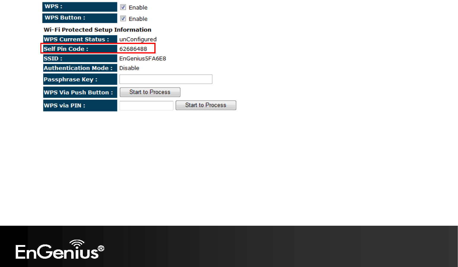
80 2. Pin Code Method Note the Pin code of your TRAVEL ROUTER device. Please use this Pin code to initialize the WPS process from the wireless client configuration utility. This process will be different for each brand or model. Please consult the user manual of the wireless client for more information.
81 Client List This page shows the wireless clients that are connected to the TRAVEL ROUTER device.
82 Policy This page allows you to configure the access policies for each SSID (wireless network). Policy WAN Connection: Allow wireless clients on this SSID to access the WAN port which typically is an Internet connection. Communication between Wireless clients: Whether each wireless client can communicate with each other in this SSID. When Disabled, the wireless clients will be isolated from each other. Communication between Wireless clients and Wired clients.
83 8.2.4 Firewall The Internet section allows you to set the access control and Firewall settings. Enable This page allows you to Enable / Disable the Firewall features. When Enabled, Denial of Service (DoS) and SPI (Stateful Packet Inspection) features are also be enabled.
84 Advanced You can choose whether to allow VPN (Virtual Private Network) packets to pass through the Firewall.
85 DMZ This feature, if enabled, allows the DMZ computer on your LAN to be exposed to all users on the Internet. • • • This allows almost any application to be used on the “DMZ PC” The “DMZ PC” will receive all Unknown connections and data. If the DMZ feature is enabled, please enter the IP address of the PC to be used as the “DMZ PC” Note: The “DMZ PC” is effectively outside the Firewall, making it more vulnerable to attacks. For this reason, you should only enable the DMZ feature when required.
86 Denial of Service (DoS) Denial of Service (Denial of Service) is a type of Internet attack that sends a high amount of data to you with the intent to overload your Internet connection. Enable the DoS firewall feature to automatically detect and block these DoS attacks.
7 MAC Filter You can choose whether to Deny or only Allow those computers listed in the MAC Filtering table to access the Internet. MAC Filter Enable MAC filtering: Tick this box to Enable the MAC filtering feature. Deny all clients with MAC addresses listed below to access the network: When selected, the computers listed in the MAC Filtering table will be Denied access to the Internet.
88 IP Filter You can choose whether to Deny or only Allow, computer with those IP Addresses from accessing certain Ports. This can be used to control which Internet applications the computers can access. You may need to have certain knowledge of what Internet ports the applications use. IP Filter Enable IP filtering: Tick this box to Enable the IP filtering feature.
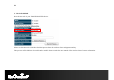
89 URL Filter You can deny access to certain websites by blocking keywords in the URL web address. For example, “abc123” has been added to the URL Blocking Table. Any web address that includes “abc123” will be blocked.
90 8.2.5 Advanced The Internet section allows you to configure the Advanced settings of the router. Network Address Translation (NAT) This page allows you to Enable / Disable the Network Address Translation (NAT) feature. The NAT is required to share one Internet account with multiple LAN users. It also is required for certain Firewall features to work properly.
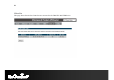
91 Port Mapping Port Mapping allows you to redirect a particular range of ports to a computer on your LAN network. This helps you host servers behind the NAT and Firewall. In the example below, there is a Mail Server that requires ports 22 to 23. When there is a connection from the Internet on those ports, it will be redirected to the Mail Server at IP address 192.168.0.150. Port Mapping Enable Port Mapping Tick this box to Enable the Port Mapping feature.
92 Port Forwarding Port Forwarding allows you to redirect a particular public port to a computer on your LAN network. This helps you host servers behind the NAT and Firewall. In the example below, there is a FTP Server running on port 21 on the LAN. For security reasons, the Administrator would like to provide this server to Internet connection on port 30. Therefore then there is a connection from the Internet on port 30, it will be forwarded to the computer with the IP address 192.168.0.
93 Port Trigger If you use Internet applications which use non-standard connections or port numbers, you may find that they do not function correctly because they are blocked by the Wireless Router's firewall. Port Trigger will be required for these applications to work. Port Trigger Enable Port Forwarding Tick this box to Enable the Port Trigger feature. Popular applications: This is a list of some common applications with preset settings.
94 Application Layer Gateway (ALG) Certain applications may require the use of ALG feature to function correctly. If you use any of the applications listed, please tick and select it to enable this feature.
95 Universal Plug and Play (UPnP) The UPnP function allows automatic discovery and configuration of UPnP enabled devices on your network. It also provides automatic port forwarding for supported applications to seamlessly bypass the Firewall. Universal Plug and Play (UPnP) Enable the UPnP Feature: Tick this box to Enable the UPnP feature to allow supported devices to be visible on the network.
96 Quality of Service (QoS) QoS allows you to control the priority that the data is transmitted over the Internet, or to reserve a specific amount of Internet bandwidth. This is to ensure that applications get enough Internet bandwidth for a pleasant user experience. If not, then the performance and user experience of time sensitive transmissions such as voice and video could be very poor.
97 Priority Queue Method Bandwidth priority is set to either High or Low. The transmissions in the High queue will be processed first. Unlimited Priority Queue Local IP Address: The computer with this IP Address will not be bound by the QoS rules. High / Low Priority Queue Protocol: The type of network protocol. High / Low Priority Sets the protocol to High or Low priority. Specific Port Each protocol uses a specific port range. Please specify the ports used by this protocol.
98 Bandwidth Allocation Method You can set the maximum amount of bandwidth a certain protocol will use at one time. Or you can set a minimum amount of bandwidth that will be guaranteed to a certain protocol. Bandwidth Allocation Type: Set whether the QoS rules apply to transmission that are Download, Upload or Both directions. Local IP range: Enter the IP address range of the computers that you would like the QoS rules to apply to.
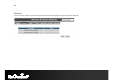
99 Routing If your TRAVEL ROUTER device is connected a network with different subnets, then this feature will allow the different subnets to communicate with each other. Note: NAT function needs to be disabled for the Routing feature to be enabled. Static Routing Enable Static Routing: Tick this box to Enable the Static Router feature. Destination LAN IP: Enter the IP address of the destination LAN.
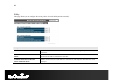
100 Destination Subnet Mask Gateway Hop Interface 192.168.1.0 255.255.255.0 192.168.123.216 1 LAN 192.168.0.0 255.255.255.0 192.168.123.103 1 LAN So if, for example, Client3 wants to send an IP data packet to 192.168.0.2 (Client 2), it would use the above table to determine that it had to go via 192.168.123.103 (Router 2) And if it sends Packets to 192.168.1.11 (Client 1) will go via 192.168.123.216 (Router 1).
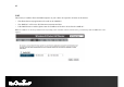
101 8.2.6 Tools This section allows you to configure some device system settings. Admin This page allows you to change the system password and to configure remote management. Change Password Old Password: Enter the current password. New Password: Enter your new password. Repeat New Password: Enter your new password again for verification. Remote Management Host Address: You can only perform remote management from the specified IP address. Leave blank to allow any host to perform remote management.
102 Time This page allows you to set the system time. Time Time Setup: Select the method you want to set the time. Time Zone: Select the time zone for your current location. NTP Time Server: Enter the address of the Network Time Protocol (NTP) Server to automatically synchronize with a server on the Internet. Daylight Savings: Check whether daylight savings applies to your area.
103 Dynamic DNS (DDNS) This free service is very useful when combined with the Virtual Server feature. It allows Internet users to connect to your Virtual Servers using a URL, rather than an IP Address. This also solves the problem of having a dynamic IP address. With a dynamic IP address, your IP address may change whenever you connect, which makes it difficult to connect to you. DDNS Services work as follows: 1. 2. 3. 4. 5. You must register for the service at one of the listed DDNS Service providers.
104 Power This page allows you to Enable or Disable the wireless LAN power saving features.
105 Diagnosis This page allows you determine if the TRAVEL ROUTER device has an active Internet connection. Diagnosis Address to Ping: Enter the IP address you like to see if a successful connection can be made. Ping Result: The results of the Ping test.
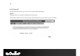
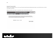
106 Firmware The firmware (software) in the TRAVEL ROUTER device can be upgraded using your Web Browser. To perform the Firmware Upgrade: 1. Click the Browse button and navigate to the location of the upgrade file. 2. Select the upgrade file. Its name will appear in the Upgrade File field. 3. Click the Apply button to commence the firmware upgrade. Note: The Wireless Router is unavailable during the upgrade process, and must restart when the upgrade is completed.
107 Back-up Back-up Restore to factory default: Restores the device to factory default settings. Backup Settings: Save the current configuration settings to a file. Restore Settings: Restores a previously saved configuration file. Click Browse to select the file. Then Upload to load the settings.
108 Reset In some circumstances it may be required to force the device to reboot.
109 8.3 AP and Client Bridge Modes When the TRAVEL ROUTER device is set to AP or Client Bridge modes, it will no longer allocate IP addresses to its wireless clients. To access the Web-Based configuration page, please follow the following steps to set a static IP address (Windows XP/Vista). 1. Connect to the TRAVEL ROUTER using an Ethernet CAT.5 LAN Cable. 2. Click Start and open Control Panel.
110 3. Windows XP, click [Network Connection] Windows Vista, click [View Network Status and Tasks] then [Manage Network Connections] 4. Right click on [Local Area Connection] and choose [Properties].
111 5. Check “Client for Microsoft Networks”, “File and Printer Sharing”, and “Internet Protocol (TCP/IP) is ticked. If not, please install them. 6.
112 7. Manually set the IP Address. Then click [OK] For example: IP Address: 192.168.0.250 Subnet Mask: 255.255.255.
113 8. You should now be able to access the Web-Based configuration in your Web Browser. 9. Remember to configure the settings back to Obtain an IP Address Automatically and Obtain DNS Server Address Automatically once you complete configuring the Web-Based interface.
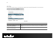
114 8.4 Client Bridge Mode The Client Bridge mode turns the TRAVEL ROUTER into a wireless client, which then allows non-wireless devices to use its RJ45 port to access the network wirelessly. 8.4.1 Wireless This section allows you to configure which wireless network the TRAVEL ROUTER will connect to. Basic 1. Configure which wireless network the TRAVEL ROUTER will connect to in the Wireless Basic page. 2. Use the Site Survey button to scan the area for available wireless networks.
115 3. Select the SSID (wireless network) that you would like to connect to, and then click Add to AP Profile. 4. Enter the wireless security settings for this SSID. Then click Save to apply the settings. 5. Change your IP Address settings back to Obtain your IP Address Automatically. You should now be connected to the wireless network through the TRAVEL ROUTER.
116 AP Profiles You can save the settings up to three wireless networks. The TRAVEL ROUTER will automatically connect to the wireless network in order of priority. AP Profile Add: Manually Add a new SSID (wireless network) profile. Edit: Edit the SSID settings. Move Up / Down: Change the priority that the TRAVEL ROUTER will connect to these SSID’s. Delete Selected: Deletes the selected SSID profile. Delete All: Deletes all SSID profiles. Connect: Force connection to this SSID.
117 Appendix A – FCC Interference Statement Federal Communication Commission Interference Statement This equipment has been tested and found to comply with the limits for a Class B digital device, pursuant to Part 15 of the FCC Rules. These limits are designed to provide reasonable protection against harmful interference in a residential installation.
118 IMPORTANT NOTE: FCC Radiation Exposure Statement: This equipment complies with FCC radiation exposure limits set forth for an uncontrolled environment. This equipment should be installed and operated with minimum distance 20cm between the radiator & your body. We declare that the product is limited in CH1~CH11 by specified firmware controlled in the USA. This transmitter must not be co-located or operating in conjunction with any other antenna or transmitter.,except the evaluated 3G co-transmitting.
119 Appendix B – IC Interference Statement Industry Canada statement: This device complies with RSS-210 of the Industry Canada Rules. Operation is subject to the following two conditions: (1) This device may not cause harmful interference, and (2) this device must accept any interference received, including interference that may cause undesired operation. IMPORTANT NOTE: Radiation Exposure Statement: This equipment complies with IC radiation exposure limits set forth for an uncontrolled environment.