Parani-MSP1000 For Wireless Multi-Serial Communications, based on Bluetooth Technology User Guide Version 0.0.
User Guide for the Parani-MSP1000 Version 0.0.1 Firmware version 1.0.X Last revised on August 16, 2007 Printed in Korea Copyright Copyright 2007, Sena Technologies, Inc. All rights reserved. Sena Technologies reserves the right to make changes and improvements to its product without providing notice. Trademark Parani™ is a trademark of Sena Technologies, Inc. Windows® is a registered trademark of Microsoft Corporation. Ethernet® is a registered trademark of XEROX Corporation.
Revision History Revision V0.0.
Contents 1. Introduction 7 1.1. Overview ....................................................................................................................................7 1.2. Package Check List....................................................................................................................8 1.3. Product Specification..................................................................................................................8 2. Getting Started 10 2.1. External View ........
6.2.1. Adding a new user .........................................................................................................32 6.2.2. Removing a user............................................................................................................32 6.2.3. Editing a user .................................................................................................................32 6.3. Certificates ..........................................................................................
Appendix 1. Connections 43 A 1.1. Ethernet Pin outs...................................................................................................................43 A 1.2. Console and Serial port pin-outs...........................................................................................43 A 1.3. Ethernet Wiring Diagram.......................................................................................................44 Appendix 2. Parani-MSP1000 Configuration files 45 A 2.1. ip.conf.....
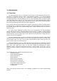
1. Introduction 1.1. Overview The Parani-MSP1000 series is a Bluetooth Access Point to enable Bluetooth devices to be connected to 10/100Mbps Ethernet network. Parani-MSP1000 supports 7, 14, and 28 Bluetooth connections according to the model, and it supports up to 3Mbps throughput through Bluetooth 2.0+EDR specification. The Parani-MSP1000 series is a class 1 Bluetooth device that supports 150m using basic dipole antenna and up to 1 km using patch antenna.
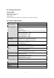
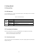
1.2. Package Check List - DC Power Adapter - Quick Start Guide - RS232 Serial Console Cable - Ethernet Cross Cable - Dipole antenna - CD-ROM, including the Serial/IP Com Port Redirector, software and manual 1.3. Product Specification Ethernet Interface Parani-MSP1000 Dual 10/100 Base-T Ethernet with RJ45 connector Supports Static IP and Dynamic IP address Bluetooth v2.0 + EDR Class 1 Level: 18dBm Frequency: 2.
* Note : Bluetooth v2.0 supports improved AFH function. AFH function is to mitigate the interference between WiFi and Bluetooth radios by automatically avoiding the active WiFi channel from Bluetooth link. However, AFH does not provide a complete solution making WiFi and Bluetooth work together in harmony. It is highly recommended for users to test their wireless system enough before deployment since the overall system performance is affected by various environmental factors such as distance between them.
2. Getting Started 2.1. External View 2.2. LED Indicators The Parani-MSP100 has a number of LED indicator lamps for status display.
Figure 2-1 Connecting the power to the Parani-MSP1000 2.3.2. Connecting to the network Plug one end of the Ethernet cable to the Parani-MSP1000 [Eth0] port. The other end of the Ethernet cable should be connected to a network port. If the cable is properly connected, the Parani-MSP1000 will have a valid connection to the Ethernet network. This will be indicated by: The [Eth0] blink to indicate incoming/outgoing Ethernet packets. Figure 2-2 Connecting a network cable to the MSP1000 2.4.
z Remote console Users who require a menu-driven interface remotely can utilize Telnet (port 23) or SSH (port 22) connections to the Parani-MSP1000 using Telnet or SSH client. The menu-driven user interface provides limited functions for initial configuration. NOTE : Please note that Parani-MSP1000 supports only the SSH v2, so user must use the SSH client which is able to support SSH v2.
Parity None Stop bits 1 No flow control 4) Press the [ENTER] key. 5) Enter your username and password to log into the Parani-MSP1000. The factory default user settings are as follows. Login: root 6) Password: root After login, users can use various shell commands in the CLI(Command Line interface). For details on the CLI, refer to the chapter 9, “CLI Guide”.
From the main menu screen, the users may select a menu item for configuration of the ParaniMSP1000 parameters by selecting the menu number and pressing the [ENTER] key. In the submenu screen, users can configure the required parameters guided by online comments. NOTE: Be sure to perform “save” and “apply” command before you exit from editconf menu program.
Figure 2-4 Login screen of the Parani-MSP1000 web management Figure 2-5 The Parani-MSP1000 Series web management screen Figure 2-5 shows the configuration homepage of the Parani-MSP1000 Web management interface.
menu bar is provided on the left side of the screen. The menu bar includes the uppermost configuration menu groups. Selecting an item on the menu bar opens a tree view of all the submenus available under each grouping. Selecting a submenu item will allow the user to modify parameter settings for that item. Every page will allow the user to [Save to Flash], [Save & apply] or [Cancel] their actions.
3. Network Configuration 3.1. ETHERNET0 (eth0) Configuration The Parani-MSP1000 requires a valid IP address to operate within the user’s network environment. If the IP address is not readily available, contact the system administrator to obtain a valid IP address for the Parani-MSP1000. Please note that the Parani-MSP1000 requires a unique IP address to connect to the user’s network. The users may choose one of two Internet protocols in setting up IP address: i.e.
each of these in more detail. Note: The Parani-MSP1000 will attempt to locate all this information every time it is turned on. z IP address A Static IP address acts as a “static” or permanent identification number. This number is assigned to a computer to act as its location address on the network. Computers use these IP addresses to identify and talk to each other on a network. Therefore, it is imperative that the selected IP address be both unique and valid in a network environment. Note: 192.168.1.
when the primary DNS server is unavailable.) 3.1.2. When using Dynamic Host Configuration Protocol (DHCP) Dynamic Host Configuration Protocol (DHCP) is a communications protocol that lets network administrators manage and automate the assignment of IP addresses centrally in an organization’s network.
The Parani-MSP1000 has two ETHERNET ports. The users may configure the secondary ETHERNET (eth1) to “Bridged with eth0” or “Bridged with pan0.” z Bridged with eth0 The eth1 will be bridged to eth0. If then, it works as a link fail-over of the eth0. When the eth0 is unplugged, the Parani-MSP1000 sends packets through eth1 instead of eth0. While in this operating, the IP address of eth1 is the IP address configured for the eth0.
logging. 3.4. Firewall Configuration The Parani-MSP1000 prevents unauthorized access using an IP address based filtering method.
Figure 3-3 IP filtering Configuration Table 3-2 Input examples of Option and IP address/mask combination Allowable Hosts Input format Option IP address/mask Any host 0.0.0.0/0.0.0.0 Normal 192.168.1.120 192.168.1.120/255.255.255.255 Normal Any host except 192.168.1.120 192.168.1.120/255.255.255.255 Invert 192.168.1.1 ~ 192.168.1.254 192.168.1.0/255.255.255.0 Normal 192.168.0.1 ~ 192.168.255.254 192.168.0.0/255.255.0.0 Normal 192.168.1.1 ~ 192.168.1.126 192.168.1.0/255.255.255.
abnormally) by either of the hosts to prevent the lock-up of the corresponding TCP port. To prevent this type of lock-up situation, the Parani-MSP1000 provides a TCP “keep-alive” feature. The ParaniMSP1000 will send packets back and forth through the network periodically to confirm that the network exists . The corresponding TCP session is closed automatically if there’s no response from the remote host.
4. Bluetooth Configuration 4.1. Overview 4.2. Device Configuration This menu is the configuration for the Bluetooth devices embedded in the Parani-MSP1000. z Bluetooth friendly name The device name. %h inserts the host name (device name) configured in the Device name configuration. %d inserts the device id. z Inquiry scan When this is enabled, the Parani-MSP1000 is “discoverable.” z Page scan When this is enabled, the Parani-MSP1000 is “connectable to.
The Parani-MSP1000 doesn’t accept any incoming connection. z Accept connection from unspecific devices The Parani-MSP1000 accepts all incoming connections. The Parani-MSP1000 doesn’t create any outgoing connection. z Initiate/accept connection to/from specific devices The Parani-MSP1000 accepts incoming connections from the registered devices and initiates outgoing connections to the registered devices. 4.3.2.
service. If the network service is client, the Parani-MSP1000 creates a outgoing connection and if the network service is server, the Parani-MSP1000 listen on a TCP port. And then, if TCP connection is established, the data received from SPP is transmitted to TCP/IP and the data received from TCP/IP is transmitted to SPP. If there are more than one registered network service, each network service operates independently.
4.3.2.1.5. Network service The available options are as follows: z Network service mode The available mode is server, client and tunneling. If the server is selected, the Parani-MSP1000 waits for incoming connection. If the client is selected, the Parani-MSP1000 tries to connect to remote hosts. If the tunneling is selected, the Parani-MSP1000 waits for incoming connection, but when there is data received from SPP and there is no incoming connection, the Parani-MSP1000 tries to connect to remote host.
connection with this interval. If the periodic connection is zero, it means that the Parani-MSP1000 never initiates connection when there is no data received from SPP. z When Bluetooth connection is established: Initiate connection or Do nothing If the “Initiate connection” is selected, the Parani-MSP1000 attempts to connect to remote host immediately when Bluetooth connection is established. However, If the “Do nothing” is selected, the Parani-MSP1000 wait until data is arrived from SPP. 4.3.3.
4.3.4.1.2. Remote BD address The Parani-MSP1000 waits for incoming connection from this BD address or tries to connect to this BD address. 4.3.4.1.3. Service category Please, refer to 4.3.2.1.1 Service category 4.3.4.1.4. Frame buffer Please, refer to 4.3.2.1.4 Frame buffer 4.3.4.1.5. Network service Please, refer to 4.3.4.1.5 Network service 4.3.4.1.6. Logging The data logging functionality is available.
Every day Every day, AM 00:00:00, Every hour Every hour, 0 minute, 0 second 4.4. PAN/DUN/LAP Configuration 4.4.1. Private address 4.4.2. Personal Area Networking (PAN) 4.4.3. Dial-Up Networking (DUN) 4.4.4.
5. CF card Configuration 5.1.
6. System administration 6.1. Device name 6.2. User management 6.2.1. Adding a new user 6.2.2. Removing a user 6.2.3. Editing a user 6.3. Certificates 6.3.1. Changing certificate 6.3.2. Changing private key 6.3.3. Uploading a new Trusted CA certificate 6.3.4. Removing a Trusted CA certificate 6.4. Date and Time 6.5. Configuration management 6.5.1. Exporting configuration 6.5.2. Importing configuration 6.5.3. Reset to factory-default 6.6. Firmware upgrade 6.7.
7. System status & log 7.1. System status 7.2. System logging 7.2.1. System log location 7.2.2. System log buffer size 7.2.3. Lessen system log 7.3.
8. System statistics 8.1. Network interfaces Network interfaces statistics displays basic network interfaces usage of the Parani-MSP1000, lo, eth0 and eth1. lo is a local loop back interface and eth0 and eth1 are network interfaces of ParaniMSP1000. Figure 8-1 Network interfaces statistics 8.2. IP The IP Statistics screen provides statistical information about packets/connections using an IP protocol.
InDelivers : Specifies the number of received datagrams delivered. OutRequests : Specifies the number of outgoing datagrams that an IP is requested to transmit. This number does not include forwarded datagrams. OutDiscards : Specifies the number of transmitted datagrams discarded. These are datagrams for which no problems were encountered to prevent their transmission to their destination, but which were discarded (for example, for lack of buffer space.
The ICMP Statistics screen provides statistical information about packets/connections using an ICMP protocol. Definitions and descriptions of each parameter are described below: InMsgs, OutMsgs : Specifies the number of messages received or sent. InErrors, OutErrors : Specifies the number of errors received or sent. InDestUnreachs, OutDestUnreachs : Specifies the number of destination-unreachable messages received or sent.
InAddrMasks, OutAddrMasks : Specifies the number of address mask requests received or sent. A computer sends an address mask request to determine the number of bits in the subnet mask for its local subnet. InAddrMaskReps, OutAddrMaskReps : Specifies the number of address mask responses received or sent. A computer sends an address mask response in response to an address mask request. Figure 8-3 ICMP statistics 8.4.
EstabResets : Specifies the number of established connections that have been reset. CurrEstab : Specifies the number of currently established connections. InSegs : Specifies the number of segments received. OutSegs : Specifies the number of segments transmitted. This number does not include retransmitted segments. RetransSegs : Specifies the number of segments retransmitted. RetransSegs : Specifies the number of errors received. OutRsts : Specifies the number of segments transmitted with the reset flag set.
9. CLI guide 9.1. Introduction The root user can access the Linux console command line interface (CLI) of the Pro Series via the serial console or TELENT/SSH. In the CLI, the user can perform standard Linux commands to view the status of the Pro Series, edit the configuration, apply configuration changes. 9.2. Flash partitions The Pro Series internal flash is partitioned as shown in the table below. The user can access files at /var directory at his own risk.
Telnet console: 1) telnet Parani-MSP1000_IP_address SSH console: 1) ssh Parani-MSP1000_IP_address 40
10. Approval Information 10.1. FCC 10.1.1. FCC Compliance Statement This device complies with part 15 of the FCC Rules. Operation is subject to the following two conditions: (1) This device may not cause harmful interference, and (2) This device must accept any interference received, Including interference that may cause undesired operation Information to User This equipment has been tested and found to comply with the limits for a Class B digital device, Pursuant to part 15 of the FCC Rules.
11. RF Information 11.1. Radio Frequency Range 2.402~2.480GHz 11.2. Number of Frequency Channel 79 channels 11.3. Transmission Method FHSS(Frequency Hopping Spread Spectrum) 11.4. Modulation Method GFSK(Gaussian-filtered Frequency Shift Keying) 11.5. Radio Output Power +18dBm 11.6. Receiving Sensitivity -88dBm 11.7.
Appendix 1. Connections A 1.1. Ethernet Pin outs The Pro Series uses a standard Ethernet connector, which is a shielded connector that is compliant with the AT&T258 specifications. Table A-1 shows the pin assignment and wire color. Figure A-1 Pin layout of the RJ45 connector Table A-1 Pin assignment of the RJ45 connector for Ethernet Pin 1 2 3 4 5 6 7 8 Description Tx+ TxRx+ NC NC RxNC NC Color White with orange Orange White with green Blue White with blue Green White with brown Brown A 1.2.
7 8 9 RTS CTS - RTSRXCTS- RX- The serial communication type can be set by DIP switch near by serial port. (Only for PS110 and PS410) To change the serial communication type, change the position of each DIP switch as shown below. But please note that the power of the Pro Series should be turned off before changing the serial communication type. Figure A-3 Serial communication type and DIP switch configuration A 1.3.
Appendix 2. Parani-MSP1000 Configuration files A 2.1. ip.
Appendix 3. Well-known port numbers Port numbers are divided into three ranges: Well Known Ports, Registered Ports, and Dynamic and/or Private Ports. Well Known Ports are those from 0 through 1023. Registered Ports are those from 1024 through 49151. Dynamic and/or Private Ports are those from 49152 through 65535. Well Known Ports are assigned by IANA, and on most systems, can only be used by system processes or by programs executed by privileged users. Table A-3 shows some of the well-known port numbers.
Appendix 4.
Appendix 5: Warranty A.5.1. GENERAL WARRANTY POLICY Sena Technologies, Inc. (hereinafter referred to as SENA) warrants that the Product shall conform to and perform in accordance with published technical specifications and the accompanying written materials, and shall be free of defects in materials and workmanship, for the period of time herein indicated, such warranty period commencing upon receipt of the Product.
- Product that has been exposed to repair attempts by a third party without SENA’s written consent, - Hardware hosting modified SENA Software, or non-SENA Software, unless modifications have been approved by SENA. - Battery component capacity degradation due to usage, aging, and with some chemistry, lack of maintenance. A.5.4. SOFTWARE PRODUCT WARRANTY DETAILS WARRANTY PERIOD: SENA warranties software Product for a period of one (1) year.