
User's Manual


45
Appendix A: Connections
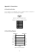
A.1 Serial Port Pin Outs
The pin assignment of the LS100W DB9 connector is summarized in Table A-1. Each pin has a
function according to the serial communication type configuration.
6 7 8 9
1 2 3 4 5
Figure A-1. Pin layout of the DB-9 connector
Table A-1. Pin assignment of the DB-9 connector
Pin RS232
1 -
2 Rx
3 Tx
4 DTR
5 GND
6 DSR
7 RTS
8 CTS
9 -
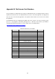
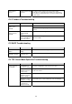
A.2 Serial Wiring Diagram
Tx(3)
Rx(2)
RTS(7)
CTS(8)
DTR(4)
DSR(6)
GND(5)
Rx
Tx
CTS
RTS
DSR
DTR
GND
HelloDevice
Serial Device
RS232
Figure A-2 RS232 wiring diagram