
User's Manual


11
2: Getting Started
This chapter describes how to set up and configure the LS100W in the first place.
- 2.1 Panel Layout explains the panel layout and LED indicators.
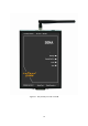
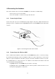
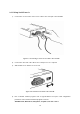
- 2.2 Connecting the Hardware describes how to connect the power, the network, and the serial
device to the LS100W.
- 2.3 Accessing Console Port describes how to access the console port using a serial console at a
local site or telnet console at a remote site.
- 2.4 Command Usages described how to use command set of the LS100W to configure and view
parameter values and status.
Following items are pre-required to get started.
- One DC power adapter (included in the package).
- One serial console cable for configuration (included in the package).
- One RS-232 serial cable for connecting the RS-232 serial device.
- One PC with Network Interface Card (hereafter, NIC) and/or one RS232 serial port.
- Terminal emulation program running on the PC
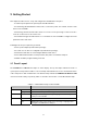
2.1 Panel Layout
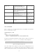
The LS100W has 5 LED indicator lamps for status display. The top two lamps indicate the status of
system power and operation readiness. The next lamp down indicates the receive and transmit status
of the serial port for data communication. The final two lamps indicate the IEEE802.11b Wireless LAN
connection and its activity, respectively. Table 2-1 describes the function of each LED indicator lamp.
Table 2-1. LED Indicator Lamps on the LS100W
Lamps Functions
Power
Solid RED when power is supplied
Status
Ready
Solid GREEN when system is running
Serial Ports Serial Rx/Tx
Blinking when there is any incoming or outgoing data stream through the
serial port of the LS100W
Link
Solid ORANGE when connected to Wireless LAN Network
Wireless LAN
Act
Blinking when there is any activity such as incoming or outgoing packets
through the LS100W Wireless LAN port.