
Datasheet


SKM400GA12V
2 Rev. 4 – 15.08.2012 © by SEMIKRON
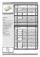
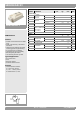
Characteristics
Symbol Conditions min. typ. max. Unit
Inverse diode
V
F
= V
EC
I
F
= 400 A
V
GE
=0V
chiplevel
T
j
=25°C
2.20 2.52 V
T
j
=150°C
2.15 2.47 V
V
F0
chiplevel
T
j
=25°C
1.3 1.5 V
T
j
=150°C
0.9 1.1 V
r
F
chiplevel
T
j
=25°C
2.3 2.5 m
T
j
=150°C
3.1 3.4 m
I
RRM
I
F
= 400 A
di/dt
off
=9500A/µs
V
GE
=±15V
V
CC
= 600 V
T
j
=150°C
450 A
Q
rr
T
j
=150°C
58 µC
E
rr
T
j
=150°C
26 mJ
R
th(j-c)
per diode 0.14 K/W
Module
L
CE
15 20 nH
R
CC'+EE'
terminal-chip
T
C
=25°C
0.18 m
T
C
=125°C
0.22 m
R
th(c-s)
per module 0.02 0.038 K/W
M
s
to heat sink M6 3 5 Nm
M
t
to terminals
M6
2.5 5 Nm
M4
1.1 2 Nm
w 330 g
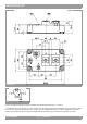
SEMITRANS
®
4
GA
SKM400GA12V
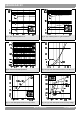
Features
• V-IGBT = 6. Generation Trench V-IGBT
(Fuji)
• CAL4 = Soft switching 4. Generation
CAL-diode
• Isolated copper baseplate using DBC
technology (Direct Copper Bonding)
• UL recognized, file no. E63532
• Increased power cycling capability
• With integrated gate resistor
• Low switching losses at high di/dt
Typical Applications*
•AC inverter drives
•UPS
• Electronic welders
• Switched reluctance motor
Remarks
• Case temperature limited to
T
c
= 125°C max, recomm.
T
op
= -40 ... +150°C, product
rel. results valid for T
j
= 150°