
Service manual

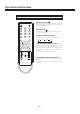

Mechanical Disassemblies
-36-
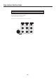
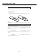
CABINETBACKREMOVAL
1.Refert o Figure 1,remove7screws.
2.Pulloffcabine t back andremove.
CHASSISREMOVAL
1.Removecabinetback.
2.Dischargethepicturetubeanode(2ndanodelead)tothe
dagcoating(picturetubegroundinglead).
3.DisconnectDegaussingcoilsocket(KE),Picturetubesocket,
D eflectionyokeconnector(KDY),Speakerconnectors(KL
andKR),and2ndanodelead.
4.Removechassiscompletelybyslidingitstraightback.
CAUTION:
Donotdisturbthedeflectionyoke
ormagnetassemblyo n th e pictur e tube
Neck.Car e mus t be takentokee p these
assembliesintact,unles s pictur e tub e is
beingreplaced.Dischargethepicturetube
tothecoatingbeforehandingth e Tube.
1.Removechassis,referringtoChassisRemovalinstructions.
2.Placecabinetfron t facedownonthesoftsurface.
3.Removethescrewoneachcornerofthepicturetubeand
GENTLYliftthepicturetubeoutofthecabinet.
4.Installareplacementpictur e tubeinreverseorder.
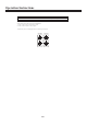
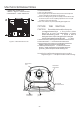
Properl y instal l thedegaussingcoilandpicturetube
groundin g leadonthepicturetube.SeeFigure2.
PICTUR
E
TUBE REMOVAL
Note:IfthePictureTubeisbeingreplaced,mountthe
DegaussingCoi l onthepicturetube.Seefollowing..
Figure1.CabinetBackRemovel
DEGAUSSING
COIL
DEGAUSSING
COILHOLDER
ToCRTUnit
ground
PICTURETUBE
GROUNDINGLEAD
DEGAUSSING
COILSOCKET