
Datasheet
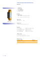

ESG 3.12
Clock-pulse generator time delay relay
MFT IT14S
Function descriptions
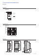
TP - Cycling timer relay beginning on a pause
When the supply voltage U is applied, the set interval t1
begins (green LED U/t flashes slowly). After the interval t1 has
expired, the output relay switches into on-position (yellow
LED illuminated) and the set interval t2 begins (green LED U/t
flashes fast). After the interval t2 has expired, the output relay
switches into off-position (yellow LED not illuminated).
The output relay is triggered in the ratio of the two set intervals
until the supply voltage is interrupted.
TI - Cycling timer relay beginning on a pulse
When the supply voltage is applied, the output relay R
switches into on-position (yellow LED illuminated) and the set
interval t1 begins (green LED U/t flashes slowly). After the
interval t1 has expired, the output relay switches into off-
position (yellow LED not illuminated) and the set interval t2
begins (green LED U/t flashes fast). After the interval t2 has
expired, the output relay switches into on-position again
(yellow LED illuminated).
The output relay is triggered in the ratio of the two set intervals
until the supply voltage is interrupted.
U
LED U/t
R
t2 t2t1 t1
U
LED U/t
R
t1 t1t2 t2