
Datasheet
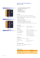
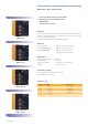

ESG 5.4
Function description
When the supply voltage U is applied, the output relays switch into on-
position (yellow LED illuminated) and the set interval of the start-up
suppression (START) begins (green LED U flashes). Changes of the
measured current during this period do not affect the state of the
output relay. After the interval has expired the green LED is illuminated
steadily.
For all the functions the LEDs MIN and MAX are flashing alternating,
when the minimum value for the measured current was chosen to be
greater than the maximum value.
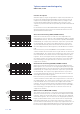
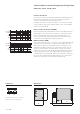
Overcurrent monitoring (OVER, OVER+LATCH)
When the measured current exceeds the value adjusted at the
MAX-regulator, the set interval of the tripping delay (DELAY) begins
(red LED MAX flashes). After the interval has expired (red LED MAX
illuminated), the output relays switch into off-position (yellow LED
not illuminated). The output relays again switch into on-position
(yellow LED illuminated), when the measured current falls below
the value adjusted at the MIN-regulator (red LED MAX not illumina-
ted).
If the error memory is activated (OVER+LATCH) and the measured
current remains above the MAX-value longer than the set interval of
the tripping delay, the output relays remain in the off-position even
if the measured current falls below the value adjusted at the MIN-
regulator. After resetting the failure (interrupting and re-applying
the supply voltage), the output relays switch into on-position and a
new measuring cycle begins with the set interval of the start-up
suppression (START).
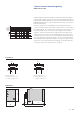
Undercurrent monitoring (UNDER, UNDER+LATCH)
When the measured current falls below the value adjusted at the
MIN-regulator, the set interval of the tripping delay (DELAY) begins
(red LED MIN flashes). After the interval has expired (red LED MIN
illuminated), the output relays switch into off-position (yellow LED
not illuminated). The output relays again switch into on-position
(yellow LED illuminated), when the measured current exceeds the
value adjusted at the MAX-regulator.
If the error memory is activated (UNDER+LATCH) and the measured
current remains below the MIN-value longer than the set interval of
the tripping delay, the output relays remain in the off-position even
if the measured current exceeds the value adjusted at the MAX-
regulator. After resetting the failure (interrupting and re-applying
the supply voltage), the output relays switch into on-position and a
new measuring cycle begins with the set interval of the start-up
suppression (START).
Window function (WIN, WIN+LATCH)
The output relays switch into on-position (yellow LED illuminated)
when the measured current exceeds the value adjusted at the MIN-
regulator. When the measured current exceeds the value adjusted
at the MAX-regulator, the set interval of the tripping delay (DELAY)
begins (red LED MAX flashes). After the interval has expired (red
LED MAX illuminated), the output relays switch into off-position
(yellow LED not illuminated). The output relays again switch into on-
position (yellow LED illuminated) when the measured current falls
below the value adjusted at the MAX-regulator (red LED MAX not
1-phase current monitoring relay
EMR SI23O, SI23P
U
LED U
LED MAX
LED MIN
LATCH
Max
Min
Start Delay Delay Delay Start
U
LED U
LED MAX
LED MIN
LATCH
Max
Min
Start Delay Delay Delay Start
U
LED U
LED MAX
LED MIN
Max
Min
Start Delay >Delay Delay