Inc. Line Thermal Printer Mechanism Reference Guide
Manuals
Brands
Seiko Instruments Manuals
Printer
LTP F Series
51
52
53
54
55
56
57
58
59
60
6-1
CHA
PT
ER 6
HOUSING DES
IGN GUIDE
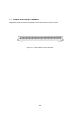
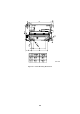
6.1
SECURING THE PRINT
ER
6.1.1
Printer Mounting Dimensions
As shown in
Figure 6-1
, secure the printer at f
our m
ounting holes: a, b, c and d.
The indents
#1 and #2 are for pos
itioning.
1
...
...
57
58
59
60
61
...
...
86