
Data Sheet

13 | P a g e Espressif Systems Oct 12, 2013
ESP8266 802.11bgn Smart Device
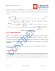
The APB block acts as a decoder. It is meant only for access to programmable registers within
ESP8266’s main blocks. Depending on the address, the APB request can go to the radio, SI/SPI,
SDIO (host), GPIO, UART, real-time clock (RTC), MAC or digital baseband.
8.4 Interfaces
The ESP8266 contains several analog and digital interfaces described in the following sections.
8.4.1 Master SI / SPI Control (Optional)
The master serial interface (SI) can operate in two, three or four-wire bus configurations to
control the EEPROM or other I2C/SPI devices. Multiple I2C devices with different device
addresses are supported by sharing the 2-wire bus.
Multiple SPI devices are supported by sharing the clock and data signals, using separate software
controlled GPIO pins as chip selects.
The SPI can be used for controlling external devices such as serial flash memories, audio
CODECs, or other slave devices. It is set up as a standard master SPI device with 3 different
enable pins:
SPI_EN0,
SPI_EN1,
SPI_EN2.
Both SPI master and SPI slave are supported with the latter being used as a host interface.
SPI_EN0 is used as an enable signal to an external serial flash memory for downloading patch
code and/or MIB-data to the baseband in an embedded application. In a host based application,
patch code and MIB-data can alternatively be downloaded via the host interface. This pin is
active low and should be left open if not used.
SPI_EN1 is usually used for a user application, e.g. to control an external audio codec or sensor
ADC, in an embedded application. This pin is active low and should be left open if not used.