
Data Sheet


PK-1000 User Manual
- 9 -
(3) If connection failed, cut your WIFI and repeat step 1 and 2.
3.2 Set up information
(1) As illustrated in Figure 12, select the ID of the anchors you want to
communicate with, their coordinates and tag ID. (If you don’t need coordinates
from PK-1000, you can leave the box unchecked. Attention: new tag ID only works
after re-powered up.)
Figure 12 Setting up anchors and tags
(2) Click on “Set” to send set up information.
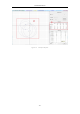
3.3 Data table and diagram
(1) As illustrated in Figure 13, in section ①, the first column shows the tag ID,
and the calculated tag coordinates. If the coordinates are not correctly calculated,
it will be (0, 0, 0). The 2
nd
to 5
th
column shows anchor-tag distances and anchor
coordinates.
(2) As illustrated in Figure 13, in section ②, every grid represents an area of
1m*1m. X-axis of this coordinate system points to the right horizontally, Y-axis
points to the top vertically. The red dot in the intersection point of X and Y axes is
the origin. The blue dots on the diagram are anchors’ locations, with their ID lying
in their bottom-right corner. Blue circles are drawn with the anchor coordinates
as the center, and distances as radius. The green dot is where the tag is, and its
coordinates are written on the bottom-right corner of this dot. You can get an
overview of how PK-1000 works clearly in this diagram: