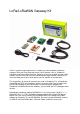
LoRa/LoRaWAN Gateway Kit LoRa is a perfect long-range wireless solution to create low-power, wide area networks.So far we have released several “LoRa” boards such as Seeeduino LoRaWan and Grove LoRa Radio etc. However if you want to build you own LoRa network, there are 3 things that you should prepare to get started: a Gateway, at least one Node and a local server where you can monitor all your devices.
Caution Please always plug 3.7V Lipo battery in case USB power supply is not sufficient. We use 868MHZ kit in this wiki, but this wiki works for both 868MHz kit and 915MHz kit.
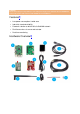
Partlist¶ Parts number Parts name Quantity ❶ Raspberry Pi 3 1 PCS ❷ Gateway module RHF0M301–868 1 PCS ❸ PRI 2 Bridge RHF4T002 1 PCS ❹ Seeeduino LoRaWAN with GPS (RHF76-052AM) 1 PCS ❺ USB to UART Adapter 1 PCS ❻ upgrade to 16GB Micro SD Card – Class 10 1 PCS ❼ 0dBi Rubber Duck Antenna 1 PCS ❽ 5V/2.1A American Standard Adapter with Micro USB Connector 1 PCS ❾ Micro USB Cable 20cm 1 PCS ❿ Micro USB Cable 100cm 1 PCS ⓫ RJ45 Ethernet Cable 200cm 1 PCS ⓬ JST2.
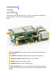
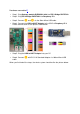
Getting Started¶ Hardware¶ Interfaces overview¶ Since there are many interfaces here, it is necessary to know the capabilities of these interfaces. Please refer to the following figure for details. • ❶ Micro-USB Input: The whole system use this Micro-USB interface for power supply. • • • • • ❷ USB HOST Connector: Output power to supply for Raspberry Pi ❸ Raspberry Pi power input: Input power for Raspberry. ❹ HDMI: HD digital video output interface. ❺ Headphone jack: 3.
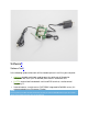
Hardware connection¶ • Step 1. Plug Gateway module RHF0M301–868 into PRI 2 Bridge RHF4T002. • Step 2. Plug PRI 2 Bridge RHF4T002 into Raspberry Pi 3. • Step 3. Connect ❷ and ❸ via the 20cm Micro-USB cable. • Step 5. Plug the USB to UART Adapter into your PC. • • Step 4. Connect the USB to UART Adapter to the GPIO of Raspberry Pi 3. Please connect them as the picture shown below. Step 6. Connect ❶ with 5V/2.1A Standard Adapter via 100cm Micro-USB cable.
Software¶ Software Tool¶ In the following guide, below tools will be needed, please install it to your computer. • Arduino, portable serial tool, used to open the serial port of Seeeduino LoRaWAN with GPS (RHF76-052AM) and send AT commands to it. • PuTTY, terminal tool include both serial and SSH terminal, used to control Raspberry Pi. • Internet browser, used to access RHF2S001 integrated LoRaWAN server (It is recommended to use Chrome or Firefox).
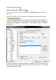
Connect To Local Server¶ Step 1. Power up and connect to putty¶ a) First, make sure the serial tool and RPi (RHF4T002 Adapter) are connected correctly. b) Plug FT232 tool to PC (If COM port is not recognized correctly, please refer to Virtual COM Port Drivers) c) Open Device Manager of your PC to get the right COM port. Like COM15 for example. Configure ExtraPuTTY according to below picture (Speed 115200, others use defaults), click Open.
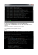
e) Please use RHF2S001 default user name and password to log in. ( Username: rxhf, Password:risinghf ). Note, when input the password, there is no any echo f) Connect RHF2S001 with router through ethernet cable g) Run ifconfig to check the ip address and mac address.
IP IS IN THE BLUE SQUARE, MAC ADDRESS IS IN ORANGE SQUARE (FORMAT: B8:27:EB:XX:XX:XX)¶ Note After you get the IP, it is recommended to login RHF2S001 again through SSH. Because SSH is faster (Ethernet than UART) and stable. We normally use serial tool to get the IP. Reopen PuTTY, use the SSH module to connect again. To login through SSH, you need to fill in the Hostname with the IP address you've just got.And use port 22,choose the SSH connection type. Just leave the other options by default.
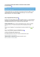
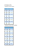
b) Frequency Plan Frequency Plan for EU868 EU868 Uplink DR CH0 867.1 DR0 ~ DR5 CH1 867.3 DR0 ~ DR5 CH2 867.5 DR0 ~ DR5 CH3 867.7 DR0 ~ DR5 CH4 867.9 DR0 ~ DR5 CH5 868.1 DR0 ~ DR5 CH6 868.3 DR0 ~ DR5 CH7 868.5 DR0 ~ DR5 Frequency Plan for US915 HYBRID US915 Uplink DR CH0 902.3 DR0 ~ DR3 CH1 902.5 DR0 ~ DR3 CH2 902.7 DR0 ~ DR3 CH3 902.9 DR0 ~ DR3 CH4 903.1 DR0 ~ DR3 CH5 903.3 DR0 ~ DR3 CH6 903.5 DR0 ~ DR3 CH7 903.7 DR0 ~ DR3 CH64 903.
c) RHF76-052AM Settings Now let's configure the Seeeduino LoRaWAN with GPS (RHF76-052AM). • Firstly, you need to connect Seeeduino LoRaWAN GPS to your PC. • Secondly, open the Arduino IDE, and copy the code blew into a new skech. 1 2 3 4 5 6 7 8 9 10 11 12 13 14 15 16 17 • void setup() { Serial1.begin(9600); SerialUSB.begin(115200); } void loop() { while(Serial1.available()) { SerialUSB.write(Serial1.read()); } while(SerialUSB.available()) { Serial1.write(SerialUSB.
• Now please open the serial monitor in the upper right corner ( or you can press Ctrl+Shift+M at the same time ).Choose Newline (This option will add "\r\n" at the end of each command.), set the baud rate 9600.Then tap the commands below and press send. For EU868 1AT+FDEFAULT=RISINGHF 2AT+DR=EU868 For US915 1 AT+FDEFAULT=RISINGHF 2 AT+DR=US915HYBRID 3 AT+RXWIN2=923.3,DR8 Caution After you plug Seeeduino LoRaWAN with GPS into your computer, you may find two serial Ports.
d) Access Internal Server Console Fill your browser with the IP address website below. (IP of your gateway) ,it Will jump to the Step 4. Use Seeeduino LoRaWAN GPS(RHF76-052AM) access LoRaWAN server¶ There are two modes,in this wiki we only talk about the ABP Mode(This Mode is free for anyone),for more information about OTAA Mode(This model is commercial, you need to pay for it),you can click here.
c) Fill in the blank with the ID info. you just get. You can fill in the name and owner as your wish (here we use Seeed and my nick name:), use the APPEui you've just got. Then click Add button.
Then you will jump into the configure page. In this page, we choose Personalised Motes. Fill in the DevEUI and DevAddr with ID info. of your Seeeduino LoRaWAN GPS. And set the NWKSKEYand APPSKEY by default. You can refer to the picture below.
d) To test whether you add the device successfully, you can use the serial monitor of Arduino IDE tap the command below. 1at+mode=lwabp 2 3AT+CMSGHEX="0a 0b 0c 0d 0e" It should like something below. Then turn to the website, click Application->Seeed(the name of the Application you just added)->View application data, you will see the data you've just sent form the Seeeduino_LoRAWAN.
Connect To Loriot Server¶ Step.1 Loriot Server Gateway Registration¶ a) New user need register an account first, click registration address . Fill in UserName, Password and email address to register, after registration an email will be sent to you, please follow the instruction in the email to activate. b) After successful activation, click here to log in. Default tier is “Community Network”, it supports 1 Gateway (RHF2S001) and 10 nodes.
g) Click “Register Raspberry Pi gateway” to finish the registration. h) Click the registered gateway to enter configuration page, switch “Frquency Plan” manually, your plan here is decided by the type of your RHF2S001 type, available plan are CN470,CN473, CN434,CN780,EU868, after selected please refresh the page to get the exact channel.In this wiki we choose EU868. i) Run the command in the putty terminal: 1cd /home/rxhf/loriot/1.0.2 2sudo systemctl stop pktfwd 3sudo gwrst 4wget https://cn1.loriot.
j) Finish gateway registration. You will see the gateway is Connected now. Next is to register node.
Step 2. Loriot Server Connect Node device¶ a) Get the available gateway channels Current gateway channels could be got from Dashboard -> Gateway -> Your Gateway , you can see the available channels as the picture below. b) Seeeduino LoRAWAN GPS(RHF3M076) Configuration Open the serial monitor of Arduino IDE, tap the command below. 1at+ch To confirm the default channel of your Seeeduino_LoRAWAN GPS, you will get 3 channels.
c) Add Seeeduino_LoRAWAN GPS as an ABP Node Log in Loriot server , Click Dash Board->Applications->SimpleApp .
d) Send data from Seeeduino_LoRAWAN Back to serial monitor of Arduino IDE, send command: 1AT+CMSGHEX="0a 0b 0c 0d 0e" Then go to Dashboard -> Applications -> SampleApp ->Device , click the Node Device EUI or DevAddr, you will find the data you've just sent here. .