UM2039 User Manual World smallest Time-of-Flight ranging and gesture detection sensor Application Programming Interface Introduction VL53L0X is a ranging and gesture detection sensor. The purpose of this User Manual is to describe the Application Programming Interface (API), and the calibration procedures from a user perspective. The API is a turnkey solution.
Contents UM2039 Contents 1 Overview . . . . . . . . . . . . . . . . . . . . . . . . . . . . . . . . . . . . . . . . . . . . . . . . . . 4 2 Initial customer manufacturing calibration . . . . . . . . . . . . . . . . . . . . . . . 5 2.1 Data init . . . . . . . . . . . . . . . . . . . . . . . . . . . . . . . . . . . . . . . . . . . . . . . . . . . 5 2.2 Static Init . . . . . . . . . . . . . . . . . . . . . . . . . . . . . . . . . . . . . . . . . . . . . . . . . . . 6 2.3 Reference SPADs calibration .
UM2039 6 7 Contents 5.1.1 Start measurement only . . . . . . . . . . . . . . . . . . . . . . . . . . . . . . . . . . . . . 15 5.1.2 Start measurement and wait for data ready . . . . . . . . . . . . . . . . . . . . . . 15 5.1.3 Start measurement, wait for data ready and report the data . . . . . . . . . 15 5.2 Stop a measurement . . . . . . . . . . . . . . . . . . . . . . . . . . . . . . . . . . . . . . . . 15 5.3 Get a result . . . . . . . . . . . . . . . . . . . . . . . . . . . . . . . . . . .
Overview 1 UM2039 Overview VL53L0X API is based on Photonic Abstraction Layer (PAL) specification. API is defined as the implementation of the PAL. The API exposes high level functions to be used by the customer application to control the device. Note: 4/26 Full API documentation is available, as part of the API package, in chm and pdf formats.
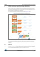
UM2039 2 Initial customer manufacturing calibration Initial customer manufacturing calibration There is an initial, once only, calibration step required that should be applied at customer level during the manufacturing process. This flow takes into account all parameters (cover glass, temperature & voltage) from the application. The customer manufacturing calibration flow is described in Figure 2 below. Figure 2.
Initial customer manufacturing calibration 2.2 UM2039 Static Init VL53L0X_StaticInit() function allows to load device settings specific for a given use case. 2.3 Reference SPADs calibration In order to optimize the dynamic of the system, the reference SPADs have to be calibrated. This step is performed on the bare modules during Final Module Test at STMicroelectronics, and the calibration data (SPAD numbers and type) are stored into the device NVM.
UM2039 2.4.1 Initial customer manufacturing calibration Ref calibration procedure User has two options: 1. Perform the calibration after VL53L0X_PerformRefSPADManagement,by calling VL53L0X_PerformRefCalibration(). 2. If user wants to improve the boot time, they can load only the calibration parameters after VL53L0X_PerformRefSPADManagement by using VL53L0X_SetRefCalibration(). This assumes that user has previously performed a calibration and stored the two parameters in the Host memory. See Section 4.
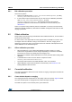
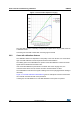
Initial customer manufacturing calibration UM2039 Figure 3. Cover window impact on ranging The cross-talk correction is basically a weighted gain applied to the ranging data, based on a calibration result. Correcting low cross-talk is easier than correcting high cross-talk. 2.6.2 Cross-talk calibration distance The calibration distance is dependent on the quality of the cover window. Low cross-talk or high cross-talk calibration cannot be performed at the same distance.
UM2039 Initial customer manufacturing calibration Figure 4. Cross-talk calibration valid distances 2.6.3 Cross-talk calibration procedure The following procedure has to be performed: Note: • Perform Offset calibration, refer to Section 2.5: Offset calibration • Choose the calibration distance, based on a ranging with cover window to be used, as described in Section 2.6.2: Cross-talk calibration distance. • Use a grey 17% reflectance target.
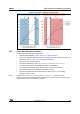
Range profile phases 3 UM2039 Range profile phases This section describes the 3 phases that are required to perform the first range measurement after reset, using the VL53L0X. There are 3 phases: • Initialization & load calibration data • Ranging • Digital housekeeping - see Section 6.2: Limit settings. 3.1 Initialization/calibration phase The initialization/calibration flow is described in Figure 5: Initialization flow on page 11.
UM2039 Range profile phases Figure 5.
/26 DocID029105 Rev 1 HOST POLLING CONTINUE GetStopCompletedStatus End Data GetRangingMeasurementD ata HOST POLLING GetMeasuremenDataReady StartContinuous POLLING NG INTERRUPT INT Data End Interrupt cleared ata CONTINUE Data GetRangingMeasu rementD ata GetRangingMeasurementD Interrupt received StartContinuous Polling/interrup t CONTINUOUS & TIMED Clear interrupt Data 1- StartSingleMeas 2- WaitDataReady (on Ranging Status) 3- GetValue API POLLING CONTINUOUS / SINGLE Data GetRa
UM2039 4 System initialization/calibration System initialization/calibration The following section shows the API function calls required to perform the system initialization, before starting the first range measurement after reset. 4.1 Data init VL53L0X_DataInit() function is called one time, and it performs the device initialization. To be called once and only once after device is brought out of reset. 4.
System initialization/calibration UM2039 Cross-talk correction value can be set using the API function VL53L0X_SetXTalkCompensationRateMegaCps(), and is enabled using VL53L0X_SetXTalkCompensationEnable(). 4.4 Device mode VL53L0X_SetDeviceMode() selects one of the following modes of operation: • Single Ranging • Continuous Ranging • Continuous Timed Ranging VL53L0X_GetDeviceMode()is used to know which mode is actually programmed. These modes are described in the VL53L0X datasheet. 4.
UM2039 Ranging 5 Ranging 5.1 Start a measurement The API allows to get a measurement in different ways, depending on the user requirements: 5.1.1 • Start measurement only • Start measurement and wait for data ready • Start measurement, wait for data ready and report the data Start measurement only VL53L0X_StartMeasurement() function must be called to start a measurement. The device will start a measurement using the chosen mode (single or continuous) 5.1.
Ranging UM2039 5.3 Get a result 5.3.1 Host polling to get the result status VL53L0X_GetMeasurementDataReady() function allows the Host to get a status on the ongoing measurement. 5.3.2 Get measurement VL53L0X_GetRangingMeasurementData() function returns the ranging data. The function returns a buffer which contains the following: RangeMilliMeter RangeDMaxMilliMeter: SignalRateRtnMegaCps AmbientRateRtnMegaCps EffectiveSpadRtnCount RangeStatus: Refer to Table 1 Table 1.
UM2039 API useful additional functions 6 API useful additional functions 6.1 Overall timing budget The timing budget is the time allocated by the user to perform one range measurement. The API takes care of splitting this timing budget into dedicated sub steps in the ranging process. The user only has to set the overall timing budget in micro seconds, and the function allocates the timings internally.
API useful additional functions UM2039 Use VL53L0X_SetLimitCheckEnable() and VL53L0X_GetLimitCheckEnable() to enable/disable a limit. The limit value is set using VL53L0X_SetLimitCheckValue() and VL53L0X_GetLimitCheckValue(). Two additional functions give access to the current value and state against which the limit is compared: VL53L0X_GetLimitCheckCurrent() and VL53L0X_GetLimitCheckStatus() Table 2 gives the default limit states and values. Table 2.
UM2039 6.5 API useful additional functions API state and API error VL53L0X_GetPalState() function gives the state of the API. All different states are given in Table 3. VL53L0X_GetPalStateString() function returns the status string. Table 3.
API useful additional functions UM2039 Table 4.
UM2039 API useful additional functions In single ranging mode, the maximum programmable threshold is 254mm. The interrupt threshold behaviour is described in Table 5. Table 5.
Example API range profiles 7 UM2039 Example API range profiles There are 4 range profiles available via API example code. Table 6. Example API range profiles 7.1 Timing budget Typical max range Typical application Default mode 30ms 1.2m (white target) standard High accuracy 200ms 1.2m (white target) precise measurement Long range 33ms 2m (white target) long ranging, only for dark conditions High Speed 20ms 1.
UM2039 Example API range profiles if (Status == VL53L0_ERROR_NONE) { Status = VL53L0_SetLimitCheckValue(pMyDevice, VL53L0_CHECKENABLE_SIGMA_FINAL_RANGE, (FixPoint1616_t)(60*65536)); } if (Status == VL53L0_ERROR_NONE) { Status = VL53L0_SetMeasurementTimingBudgetMicroSeconds(pMyDevice, 33000); } if (Status == VL53L0_ERROR_NONE) { Status = VL53L0_SetVcselPulsePeriod(pMyDevice, VL53L0_VCSEL_PERIOD_PRE_RANGE, 18); } if (Status == VL53L0_ERROR_NONE) { Status = VL53L0_SetVcselPulsePeriod(pMyDevice, VL53L0_VCSEL_P
Acronyms and abbreviations 8 UM2039 Acronyms and abbreviations Table 7.
UM2039 9 Revision history Revision history Table 8. Document revision history Date Revision 02-Jun-2016 1 Changes Initial release.
UM2039 IMPORTANT NOTICE – PLEASE READ CAREFULLY STMicroelectronics NV and its subsidiaries (“ST”) reserve the right to make changes, corrections, enhancements, modifications, and improvements to ST products and/or to this document at any time without notice. Purchasers should obtain the latest relevant information on ST products before placing orders. ST products are sold pursuant to ST’s terms and conditions of sale in place at the time of order acknowledgement.