
Data Sheet

DocID029104 Rev 2 21/40
VL53L0X Control interface
37
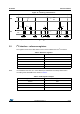
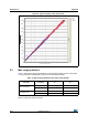
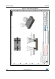
Figure 19. I
2
C timing characteristics
All timings are measured from either V
IL
or V
IH
.
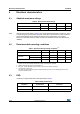
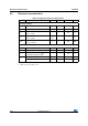
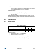
3.2 I
2
C interface - reference registers
The registers shown in the table below can be used to validate the user I
2
C interface.
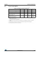
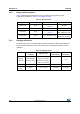
Note: I2C read/writes can be 8,16 or 32-bit. Multi-byte reads/writes are always addressed in
ascending order with MSB first as shown in
Table 5.
SDA
SCL
t
HD.STA
t
R
t
HIGH
t
F
t
SU.DAT
t
HD.DAT
t
SU.STA
t
SU.STO
...
...
t
HD.STA
t
LOW
t
BUF
stopstartstop start
V
IH
V
IL
V
IH
V
IL
Table 4. Reference registers
Address (After fresh reset, without API loaded)
0xC0 0xEE
0xC1 0xAA
0xC2 0x10
0x51 0x0099
0x61 0x0000
Table 5. 32-bit register example
Register address Byte
Address MSB
Address + 1 ..
Address + 2 ..
Address + 3 LSB