
Data Sheet

Control interface VL53L0X
20/40 DocID029104 Rev 2
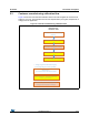
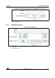
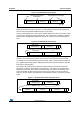
Figure 18. VL53L0X data format (sequential read)
3.1 I
2
C interface - timing characteristics
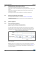
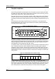
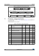
Timing characteristics are shown in Table 3. Please refer to Figure 19 for an explanation of
the parameters used.
Timings are given for all PVT conditions.
S Ac
ADDRESS[7:0]
INDEX[7:0]
Ac P
0x52 (write)
S Ac
ADDRESS[7:0]
Am
DATA[7:0]
P
0x53 (read)
Am
DATA[7:0]
Am
DATA[7:0]
Am
DATA[7:0]
Am
DATA[7:0]
Table 3. I
2
C interface - timing characteristics
Symbol Parameter Minimum Typical Maximum Unit
F
I2C
Operating frequency (Standard and
Fast mode)
0-400
(1)
1. The maximum bus speed is also limited by the combination of 400pF load capacitance and pull-up resistor.
Please refer to the I
2
C specification for further information.
kHz
t
LOW
Clock pulse width low 1.3 - - μs
t
HIGH
Clock pulse width high 0.6 - - μs
t
SP
Pulse width of spikes which are
suppressed by the input filter
- - 50 ns
t
BUF
Bus free time between transmissions 1.3 - - ms
t
HD.STA
Start hold time 0.26 - - μs
t
SU.STA
Start set-up time 0.26 - - μs
t
HD.DAT
Data in hold time 0 - 0.9 μs
t
SU.DAT
Data in set-up time 50 - - ns
t
R
SCL/SDA rise time - - 120 ns
t
F
SCL/SDA fall time - - 120 ns
t
SU.STO
Stop set-up time 0.6 - - μs
Ci/o Input/output capacitance (SDA) - - 10 pF
Cin Input capacitance (SCL) - - 4 pF
C
L
Load capacitance - 125 400 pF