
Data Sheet

Functional description VL53L0X
16/40 DocID029104 Rev 2
2.7 Getting the data: interrupt or polling
User can get the final data using a polling or an interrupt mechanism.
Polling mode: user has to check the status of the ongoing measurement by polling an API
function.
Interrupt mode: An interrupt pin (GPIO1) sends an interrupt to the host when a new
measurement is available.
The description of these 2 modes is available in the VL53L0X API User Manual.
2.8 Device programming and control
Device physical control interface is I
2
C, described in Section 3: Control interface.
A software layer (API) is provided to control the device. The API is described in the
VL53L0X API User Manual.
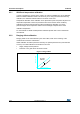
2.9 Power sequence
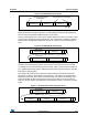
2.9.1 Power up and boot sequence
There are two options available for device power up/boot.
Option 1: XSHUT pin connected and controlled from host.
This option helps to optimize power consumption as the VL53L0X can be completely
powered off when not used, and then woken up through host GPIO (using XSHUT pin).
HW Standby mode is defined as the period when AVDD is present and XSHUT is low.
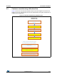
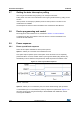
Figure 10. Power up and boot sequence
t
BOOT
is 1.2ms max.
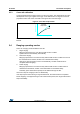
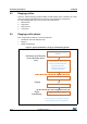
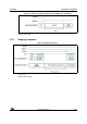
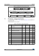
Option 2: XSHUT pin not controlled by host, and tied to AVDD through pull-up resistor.
In case XSHUT pin is not controlled, the power up sequence is presented in Figure 11. In
this case, the device is going automatically in SW STANDBY after FW BOOT, without
entering HW STANDBY.