
User Guide

IoT into the Wild
34
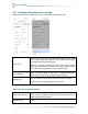
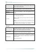
Sensor Warm-up Time
The warm-up time denotes the amount of time it takes for the
sensor to attain its highest accuracy or performance level once the
voltage supply has been applied.
Current Range
0~10V (The Data Logger can collect voltage signals within 0~10V
and automatically adjust the upper limit to increase accuracy)
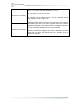
Interface V1
The Data Logger supports two analog voltage signals. When the
sensor wire is connected to V1/V2, the configuration can be
enabled.
Interface V2
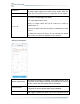
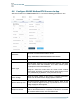
Y= Ax + B
“Y”: It is the value Datalogger will upload.
“x”: It is the original current value.
Factory A: Custom values that can be scaled up or down by
multiples of the “x”.
Factory B: A custom value that increments or diminishes the value
of the “x”.
By setting the values of A and B, you can calculate the desired
value. If only raw values are uploaded, set A=1 and B=0.
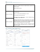
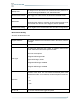
Work Mode:
Periodic collect mode
Periodically collect data. For example, if the uplink interval is set to
60 minutes, the data logger wakes up from the sleep state every 60
minutes, collects data, and uploads data via LoRaWAN.
Threshold mode
You can set a threshold rule for the measured value. When the rule
is triggered, the device uploads data through LoRaWAN.
Collect Interval
Data Logger is divided into uplink interval and collection interval.
The uplink interval is the interval of LoRaWAN data is uploaded
each time. In periodic mode, the uplink interval is equal to the
collection interval.
Range: 30~3600 seconds