THE NEW GENERATION LORAWAN SENSORS OF SENSECAP S2100 LoRaWAN Data Logger User Guide Version: v1.0.
Table of Contents 1. Product Introduction ................................................................................... 4 2. Part List ........................................................................................................ 5 3. Quick Start.................................................................................................... 6 3.1 Sensor Configuration Example ................................................................................ 6 4.
6.6 Configure RS485 Modbus-RTU Sensor via App .................................................... 36 7. Connect to the SenseCAP Portal ............................................................. 40 7.1 SenseCAP Portal................................................................................................... 40 7.1.1 Create a New Account .............................................................................................. 40 7.1.2 Other Functions ....................................
11.3 How to send downlink....................................................................................... 61 12. Device Installation ..................................................................................... 62 12.1 Check the waterproof performance of the device.............................................. 62 12.1.1 Data logger connection port ...................................................................................... 62 12.1.2 The connection port of the junction box ......
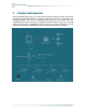
IoT into the Wild 1. Product Introduction S2100 LoRaWAN Data Logger can collect data from different types of sensors and transfer the data through LoRaWAN network. If you have deployed sensors that are not based on the LoRaWAN network, then with our LoRaWAN data logger, you can change them into LoRaWAN-based sensors and use the LoRaWAN network to transfer data.
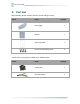
IoT into the Wild 2. Part List Before installing, please check the part list to ensure nothing is missing.
IoT into the Wild 3. Quick Start Refer to the following steps for quick configuration with SenseCAP server. Step Description Section 1 Hook up the sensor probe Section 4 2 Download SenseCAP Mate App Section 6.1 3 Configure the LoRaWAN parameters Section 6.3 Section 6.4 for level / pulse sensor 4 Configure the sensor protocol Section 6.5 for analog sensor Section 6.6 for RS485 sensor 5 Join LoRaWAN network server Section 7.2 or 7.3 6 Check the data from SenseCAP Dashboard or Section 7.
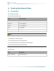
IoT into the Wild 4. Hook up the Sensor Probe 4.1 Preparation 4.1.1 Sensor Probe Get one of these sensors ready: Type Sensor wire pin RS485 Modbus-RTU 1 x A, 1 x B, 1 x GND, 1 x VCC 4~20 mA 1 or 2 x signal pin 0~10V 1 or 2 x signal pin Level 1 x signal pin Pulse Count 1 x signal pin Note: Each Data logger can only be connected to one type of sensor. For example 1. a RS485 sensor with one address 2. a 4~20mA sensor with 1or 2 measurements 3.
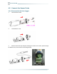
IoT into the Wild 4.2 Connect the Sensor Probe 4.2.1 Disassemble the Data Logger 1. Unscrew three screws. 2. Take down the cover. 3. Remove the thread cap and pass it through the cable of the sensor, pass it through the bottom cover, and connect it to the wiring terminal.
IoT into the Wild No. Pin Description External 12V input voltage. The Data Logger can be powered by an external 12V DC power supply. 1 12V When using 12V power supply, the battery will serve as backup power supply. 2 5V 5V output voltage, providing 5V voltage to the sensor. 3 3V 3V output voltage, providing 3V voltage to the sensor.
IoT into the Wild 4.2.3 How to install external 12V DC When your sensor needs 12V power, the battery will not be able to drive the sensor. Therefore, an external 12V power supply is required. The SenseCAP ONE Weather Station is used as an example. 1) Prepare the following items: 12V DC adapter, Junction box, and 4-pin wire. 2) Wire to the terminal of the Data Logger. Connect the cover, rubber ring and screw cap in turn.
IoT into the Wild 3) Wire to the terminal of the junction box. 4) Connect the sensor wire to the junction box.
IoT into the Wild 5) Connect the 12V DC adapter to the power supply. 6) To complete the assembly. 7) Tighten the screws and screw caps to check the waterproofing. If the wire diameter is too thin, add waterproof tape for winding.
IoT into the Wild 13
IoT into the Wild 5. LED of Sensor Working Status You can refer to the LED indicator for the Sensor Node for its working status. Please see the status explanations in the chart below: Actions First power up, press and hold for 3s Description Power on and activate the Bluetooth Green LED Status Green LED flashes at 1s frequency, waiting for Bluetooth connection. If Bluetooth not connected within 1 minute, the device would shut down again. 1. The green LED will be on for 5 seconds for initialization.
IoT into the Wild 1. Waiting for Bluetooth connection: green LED flashes at 1s frequency Press and hold for 3s Activate Bluetooth again 2. Enter configuration mode after Bluetooth connection is successful: green LED flashes at 2s frequency If Bluetooth is not connected within 1 minute, the device will reboot and join LoRa network. Press and hold for 9s Power off In the 3rd seconds will start flashing at 1s frequency, until the light is steady on, release the button, the light will go out. Note: 1.
IoT into the Wild 6. SenseCAP Mate App 6.1 Download App As a tool, SenseCAP Mate App is used to config LoRa parameters, set interval, bind devices to your account and check device basic information. (1) For iOS, please search for “SenseCAP Mate” in the App Store and download it. (2) For Android, please search for “SenseCAP Mate” in the Google Store and download it. You can also download App from https://www.pgyer.
IoT into the Wild 6.2 How to connect sensor to App 6.2.1 Create a New Account SenseCAP Mate supports device configuration and remote management. To use the SenseCAP Portal platform and other functions, please register an account. SenseCAP Mate supports offline functionality, and you can opt out of an account if you only use the configuration sensor. Just click Skip. Please select Global of Server Location. You can also create an account via the SenseCAP Portal: http://sensecap.seeed.
IoT into the Wild 6.2.2 Connect to Sensor to App 1) Press button and hold for 3 seconds, the LED will flash at 1s frequency. Please use the App to connect the sensor within 1 minute; otherwise, the device will power off or reboot. 2) Please select “S2100 Data Logger”. Please click the “Setup” button to turn on Bluetooth and click “Scan” to start scanning the sensor's Bluetooth. 3) Select the Sensor by S/N (S/N is on the front label of the sensor).
IoT into the Wild 4) Enter configuration mode after Bluetooth connection is successful: LED flashes at 2s frequency.
IoT into the Wild 6.3 Configure basic parameters through App 6.3.1 Select the Platform and Frequency S210x Sensors are manufactured to support universal frequency plan from 863MHz ~928MHz in one SKU. That is to say, every single device can support 7 frequency plans. Platform Description Default platform. SenseCAP for The Things Network It must be used with SenseCAP Outdoor Gateway (https://www.seeedstudio.com/LoRaWAN-Gateway-EU868-p4305.html ).
IoT into the Wild 1) SenseCAP for Helium: We provide the SenseCAP Portal to manage devices and data: sensecap.seeed.cc We built a private Helium Console with an embedded SenseCAP Portal. When users get the SenseCAP sensors, you can use it by scanning the code and binding it to the Portal. “SenseCAP for Helium” is selected by default. The device runs in a fixed main frequency and sub-band, refer to Helium Frequency Plan (https://docs.helium.com/lorawan-onhelium/frequency-plans/ ).
IoT into the Wild AS923-1 Need to contact sales to purchase. AS923-2 Need to contact sales to purchase. 3) Helium Users can choose sensors to use on the public helium console: https://console.helium.com/ 4) The Things Network Users can choose sensors to use on the public The Things Network server: https://console.cloud.thethings.network/ 5) Other Platform: When you use other LoRaWAN network server, please select Other Platform.
IoT into the Wild Sensor Frequency Common Name Sub-band EU863-870 EU868 -------- US902-928 US915 Sub band from 1 to 8 (default sub-band 2) AU915-928 AU915 Sub band from 1 to 8 (default sub-band 2) KR920-923 KR920 -------- IN865-867 IN865 -------- AS923-1 AS923-2 AS923 Frequency plan for Helium AS923-3 AS923-4 RU864-867 RU864 -------- Note1: Different countries and LoRaWAN network servers use different frequency plans. For Helium network, please refer to: https://docs.helium.
IoT into the Wild 6.3.2 Set the Interval The working mode of device: wake up the device every interval and collect measurement values and upload them through LoRa. For example, the device collects and uploads data every 60 minutes by default. Parameter Type Uplink Interval Unit: minutes, number from 1 to 1440. Note: The SenseCAP portal has a limit on uplink interval: minimum interval is 5 minutes. The interval using the other platforms ranges from 1 to 1440 minutes. 6.3.
IoT into the Wild 6.3.4 Set the Packet Policy The sensor uplink packet strategy has three modes. Parameter Description 2C+1N (default) 2C+1N (2 confirm packets and 1 none-confirm) is the best strategy, the mode can minimize the packet loss rate, however the device will consume the most data packet in TTN, or date credits in Helium network. 1C 1C (1 confirm) the device will sleep after get 1 received confirm packet from server.
IoT into the Wild Note: The factory defaults to a fixed key for ABP mode. 6.3.6 Restore Factory Setting When selecting the SenseCAP platform, you must use the fixed EUI/App EUI/App Key. Therefore, you need to restore the factory Settings before switching back to the SenseCAP platform from other platforms. When we make a mistake or want to reset everything, we can click the button. The device will be restored to the factory's default configuration.
IoT into the Wild 6.4 Configure Level or Pulse Sensor via App 1) Select the “GPIO” protocol. 2) Select the supply voltage to the sensor. It supports 3V/5V/12V. Please refer to section "Power Supply Options of Sensor". 3) Set the “Sensor Warm-up time”, the warm-up time denotes the amount of time it takes for the sensor to attain its highest accuracy or performance level once the voltage supply has been applied.
IoT into the Wild Wake up the data logger when the input signal is high or low and upload the current level. If no, the data logger uploads data every uplink interval. Threshold mode For example, the upload interval is set to 60 minutes, and the threshold mode is set to collect high level. When the input signal changes from a low level to a high level, the Data Logger reports the high level. If the threshold is not triggered, the current status is uploaded every 60 minutes. 6.4.
IoT into the Wild Sensor Warm-up Time The warm-up time denotes the amount of time it takes for the sensor to attain its highest accuracy or performance level once the voltage supply has been applied. Sets the type of input pulse. Digital input Pull High: Valid when a rising edge is detected. Pull Low: Valid when a falling edge is detected. Digital Filter When the pulse width exceeds 250 μs, which advised to enable it. It is enabled by default.
IoT into the Wild Enabling this function increases upload by a value: cumulative amount per hour. Unit time collection For example, if the value of Y within one hour is 1000, 1000/h will be uploaded.
IoT into the Wild 6.5 Configure Analog Sensor via App Select the “Protocol” as “Analog input”. Then set the following parameters in turn. Periodic power: Power the sensor before data collection, and power off the sensor after data collection. This mode reduces power consumption and increases battery life. Power Type Power Voltage Always-on: Select this mode when the sensor needs constant power supply. Generally, an external 12V DC power supply is used.
IoT into the Wild Interface I1 Interface I2 The Data Logger supports two analog current signals. When the sensor wire is connected to I1/I2, the configuration can be enabled. “Y”: It is the value Datalogger will upload. “x”: It is the original current value. Y= Ax + B Factory A: Custom values that can be scaled up or down by multiples of the “x”. Factory B: A custom value that increments or diminishes the value of the “x”. By setting the values of A and B, you can calculate the desired value.
IoT into the Wild The uplink interval is the interval of LoRaWAN data is uploaded each time. In periodic mode, the uplink interval is equal to the collection interval. Range: 30~3600 seconds The threshold mode greatly increases power consumption and is not recommended. Interface I1 Threshold Value = “Y”, it is the value calculated by Y= Ax+B. You can choose one of the four rules. For example, set the uplink interval = 60 min, collection interval =30s, interface I1 rule is value≥20.
IoT into the Wild Sensor Warm-up Time The warm-up time denotes the amount of time it takes for the sensor to attain its highest accuracy or performance level once the voltage supply has been applied. Current Range 0~10V (The Data Logger can collect voltage signals within 0~10V and automatically adjust the upper limit to increase accuracy) Interface V1 Interface V2 The Data Logger supports two analog voltage signals. When the sensor wire is connected to V1/V2, the configuration can be enabled.
IoT into the Wild Value = “Y”, it is the value calculated by Y= Ax + B. You can choose one of the four rules. Interface V1 Threshold For example, set the uplink interval = 60 min, collection interval =30s, interface I1 rule is value≥20. Datalogger collects data on port I1 every 30 seconds. The collected data matches the rules. If the value is greater than 20, the data is uploaded immediately. If the threshold rule is not triggered within 60 minutes, data will be uploaded once every 60 minutes.
IoT into the Wild 6.6 Configure RS485 Modbus-RTU Sensor via App Select the “Protocol” as “RS485 Modbus RTU”. Then set the following parameters in turn. Baud rate of communication with the sensor. Baud Rate Range: 4800/9600/14400/19200/38400/57600/115200 Modbus Address Slave address of the sensor. The range is 1 to 247. Periodic power: Power the sensor before data collection, and power off the sensor after data collection. This mode reduces power consumption and increases battery life.
IoT into the Wild Startup Time The length of time the sensor can communicate from powered -on to communicating with Modbus, unit: 100 milliseconds. Measurement Number Data Logger can collect 0 to 10 measurements in RS485 mode. Periodic collect mode: Periodically collect and upload data. Work Mode Measurement Setting Threshold mode: Select a maximum of three measurements to set the threshold rule. After the rule is triggered, data is uploaded.
IoT into the Wild “x”: It is the original current value. Factory A: Custom values that can be scaled up or down by multiples of the “x”. Factory B: A custom value that increments or diminishes the value of the “x”. By setting the values of A and B, you can calculate the desired value. If only raw values are uploaded, set A=1 and B=0.
IoT into the Wild Measurement Threshold 1 Measurement: Select a measurement value that has been configured. Measurement Value = “Y”, it is the value calculated by Y= Ax+B. You can choose one of the four rules. Measurement Threshold 2 For example, set the uplink interval = 60 min, collection interval =30s, interface I1 rule is value≥20. Datalogger collects data on port I1 every 30 seconds. The collected data matches the rules. If the value is greater than 20, the data is uploaded immediately.
IoT into the Wild 7. Connect to the SenseCAP Portal 7.1 SenseCAP Portal The main function of the SenseCAP Portal is to manage SenseCAP devices and to store data. It is built on Azure, a secure and reliable cloud service from Microsoft. You can apply for an account and bind all devices to this account. SenseCAP provides the web portal and API. The web portal includes Dashboard, Device Management, Data Management, and Access Key Management, while API is open to users for further development. 7.1.
IoT into the Wild 7.1.2 Other Functions Dashboard: Including Device Overview, Announcement, Scene Data, and Data Chart, etc. Device Management: Manage SenseCAP devices. Data Management: Manage data, including Data Table and Graph section, providing methods to search for data. Subaccount System: Register subaccounts with different permissions. Access Key Management: Manage Access Key (to access API service), including Key Create, Key Update, and Key Check.
IoT into the Wild 7.2 Connect to SenseCAP with Helium Network 7.2.1 Quick Start Follow this process to quickly use the sensor, see the following section for details. 7.2.2 Preparation 1) SenseCAP Mate App Download the App, please refer to section 5 for using. 2) Coverage of Helium network Option 1: Use the Helium network that already exists nearby. Please refer to the map, search your location to see if there's any helium network around: https://explorer.helium.
IoT into the Wild A green hexagon indicates the presence of the network. Option 2: Deploy a new Helium gateway. You can purchase M1, M2 gateways to cover your surroundings with the Helium network: https://www.sensecapmx.com/ 7.2.3 Bind Sensor to SenseCAP Portal Please open SenseCAP Mate App. (1) Scan QR Code 1) Click “Add device” on the upper-right corner of device page to enter the device binding page. 2) Scan the QR code on the device to bind the device to your account.
IoT into the Wild (2) Manually fill in the EUI If the QR code sticker is damaged, you can manually fill in the EUI of the device to bind the device to your account. Please make sure you put in the EUI in the format suggested by the system and then click “confirm”.
IoT into the Wild 7.2.4 Setup the Sensor 1) Open the SenseCAP Mate App 2) Press button and hold for 3 seconds, the LED will flash at 1s frequency. 3) Please click the “Setup” button to turn on Bluetooth and click “Scan” to start scanning the sensor's Bluetooth. 4) Select the Sensor by S/N (label). Then, the basic information of the sensor will be displayed after entering.
IoT into the Wild 7.2.5 Set Frequency of Sensor via SenseCAP Mate App Set the corresponding frequency band based on the frequency band of the gateway. Please refer to section 5 for detail. 1) Click the “Setting” and select the platform is “SenseCAP for Helium”.
IoT into the Wild 2) Select the Frequency Plan, if the gateway is US915, set the sensor to US915. 3) Click the “Send” button, send the setting to the sensor for it to take effect. 4) Click the “Home” button, the App will disconnect the Bluetooth connection. Then, the sensor will reboot. 5) When the device is disconnected from Bluetooth, the LED lights up for 5 seconds and then flashes as a breathing light. 6) After joining the network successfully, LED flashes fast for 2s. 7.2.
IoT into the Wild 48
IoT into the Wild 7.3 Connect to SenseCAP with private TTN 7.3.1 Quick Start Follow this process to quickly use the sensor, see the following section for details. 7.3.2 Preparation 1) SenseCAP Mate App Download the App, please refer to section 5 for using. 2) SenseCAP Outdoor Gateway Now, the sensor needs to be used with the SenseCAP Outdoor Gateway (https://www.seeedstudio.com/LoRaWAN-Gateway-EU868-p-4305.html) to transmit data to the SenseCAP Portal.
IoT into the Wild b) Bind the gateway to SenseCAP Portal. c) Ensure the gateway indicator is steady on. d) Ensure the gateway is displayed online on the portal. 7.3.3 Bind Sensor to SenseCAP Portal Please refer to the section 6.2.3 7.3.4 Setup the Sensor Please refer to the section 6.2.4 7.3.5 Set Frequency of Sensor via SenseCAP Mate App Set the corresponding frequency band based on the frequency band of the gateway. Please refer to section 5 for detail.
IoT into the Wild 2) Select the Frequency Plan, if the gateway is US915, set the sensor to US915. 3) Click the “Send” button, send the setting to the sensor for it to take effect. 4) Click the “Home” button, the App will disconnect the Bluetooth connection. Then, the sensor will reboot. 5) When the device is disconnected from Bluetooth, the LED lights up for 5 seconds and then flashes as a breathing light. 6) After joining the network successfully, LED flashes fast for 2s. 7.3.
IoT into the Wild 8. Connect to Helium Network Please refer to the manual to connect sensors to Helium public console: https://files.seeedstudio.com/products/SenseCAP/S210X/How%20to%20Connect%20Sense CAP%20S210X%20to%20Helium%20Network.pdf 9. Connect to The Things Network Please refer to this manual: https://files.seeedstudio.com/products/SenseCAP/S210X/How%20to%20Connect%20Sense CAP%20S210X%20to%20The%20Things%20Network.
IoT into the Wild 10. Payload Decoder 10.1 Decoder Code TTN payload decoding script for SenseCAP LoRaWAN: https://github.com/Seeed-Solution/TTN-Payload-Decoder/blob/master/decoder_new-v3.
IoT into the Wild 10.2 Packet Parsing 10.2.1 Packet Initialization After being powered on or reboot, SenseCAP Sensors will be connected to the network using the OTAA activation method.
IoT into the Wild 10.3 Data Parsing Example 10.3.1 Measurements List Measurements Measurement ID(HEX/DEC) Resolution Unit Air Temperature 0x1001 4097 0.01 ℃ Air Humidity 0x1002 4098 0.01 %RH Light Intensity 0x1003 4099 1 Lux CO2 0x1004 4100 1 ppm Soil Temperature 0x1006 4102 0.1 ℃ Soil Moisture 0x1007 4103 0.1 % Soil EC (Electrical Conductivity) 0x100C 4108 0.01 dS/m For the complete list, see: https://sensecap-docs.seeed.cc/measurement_list.
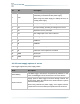
IoT into the Wild 10.3.2 Example – S2101 Air Temperature and Humidity Sensor Air Temperature and Humidity Sensor measurement packet: 01 0110 B0680000 01 0210 88F40000 8CFF Part Value Raw Data Description 01 is the channel number. 1 Air 01 0110 B0680000 Temperature 0110 is 0x1001(little-endian byte order), which is the measurement ID for air temperature. B0680000 is actually 0x000068B0, whose equivalent decimal value is 26800.
IoT into the Wild 10.4 Battery Information Please note the counter number. After 20 packets, it will follow one special packet with battery info. You can either ignore this packet or get rid of the battery info in your code. Original Info: 00070064000500010610B45F0000010710A41F00003259 Battery Package: 00070064000500 Example: Battery & Soil Moisture and Temperature Sensor(S2104) measurement packet: 00070064000500010610B45F0000010710A41F00003259 Part Value Raw Data Description 00 is the channel number.
IoT into the Wild measurement value for soil temperature as 24.5℃. 01 is the channel number. 3 4 0710 is 0x1007 (little-endian byte order), which is the measurement ID for soil moisture. Soil Moisture 01 0710 A41F0000 CRC 3259 A41F0000 is actually 0x00001FA4, whose equivalent decimal value is 8100. Divide it by 1000, and you will get the actual measurement value for soil moisture as 8.1% RH. The CRC verification part.
IoT into the Wild 11. LoRaWAN Downlink Command 11.1 Set the Data Uplink Interval (1) Using the Network Server’s portal or API to send downlink command, then the Node will respond to the ack. The downlink command takes effect and responds the next time the node uploads data.
IoT into the Wild Example: Set the Node’s data interval is 10 minutes.
IoT into the Wild 11.
IoT into the Wild 12. Device Installation 12.1 Check the waterproof performance of the device 12.1.1 Data logger connection port 1) Check the connection position of the probe of the Datalogger to ensure that the screw cap is tightened. 2) The waterproof tape can be used to wrap the connection around many circles to strengthen the waterproof performance. 12.1.2 The connection port of the junction box 12.2 Installing Sensor 12.2.
IoT into the Wild 1) With the sensor in one hand and a bracket in the other, find an unobstructed direction along the back of the sensor. 2) One hand holds the clasp while the other holds the device. Pull outward with opposite force. Press the upper part of the buckle with your finger. 12.2.
IoT into the Wild 2) Mount on wall 64
IoT into the Wild 12.3 Replace the Battery 12.3.1 How to Buy the Battery We suggest buying it from Amazon. 1) EEMB ER34615: Click here 2) Search the key word: LiSOCI2 ER34615 battery. Compare the batteries that meet the following parameters. The most important thing is to match the voltage. Battery Specification Nominal capacity 19000mAh Model Li-SOCl2, ER34615 Nominal voltage 3.6V Max. continuous current 230mA Max. pulse current capability 400mA ∅ 34.0*61.
IoT into the Wild 12.3.2 How to Replace a New Battery 1) Remove three screws. Note: The sensor and PCBA are connected by wire, please disassemble carefully. 2) Install a new battery. Note: Pay attention to the positive and negative terminals of the battery.
IoT into the Wild 3) Install screws. Note: During the installation, ensure that the waterproof washer is properly installed and the screws are locked; otherwise, water will flow into the device.
IoT into the Wild 13. Trouble Shooting 13.1 Sensors can’t join LoRa network, how to do? 1) Check the gateway frequency configuration. Make sure the gateway and Sensor Node have the same uplink and downlink frequency. 2) Check the real-time log and RESET the sensor to see if there are any sensor data packets. If there are packets, check whether the gateway is sending downlink packets.