
Data Sheet

RF Explorer User Manual page 10
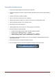
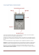
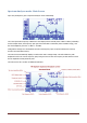
The available indicators are:
USB / battery status: this indicator will display USB
1
when a valid 5V USB connection is available.
This will be true even if the connection is through a wall wart charger, so it does not actually means a
data connection but a power bus connection. Alternatively, a battery icon with charge level indicator
will display when the RF Explorer unit power switch is set to ON. If both connections are enabled,
then USB and Battery will alternate and, in this case, the battery will be charging.
Sweeps per second: this is an approximate value of the number of full screen sweeps happening
every second. In the example above, there are 5 sweeps per second or, in equivalent terms, one
sweep every 200ms.
Calculator mode: this indicator may have different values as specified by the Calculator mode in the
frequency menu. Please check the section Frequency Menu in page 15.
DSP mode: this indicator shows the actual value being used by the Analyzer. The
DSP:Auto
is the
recommended setting in the Frequency Menu (see page 15) so RF Explorer will select the best
possible option as per below:
o FST: Fast mode. This is the standard mode available in all models.
o FIR: Filter mode. This is available in the 15-2700MHZ and Plus modules only, and is the
recommended one for those models.
Marker: There are different operational modes for the marker, see Configuration Menu in page 21.
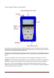
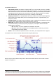
The analyzer screen can be turned into advanced mode using the [Return] key:
Note the frequency axis indicators changes at the bottom. More details about this screen mode in section
Analyzer screen
page 17.
1
USB refers to Universal Serial Bus, the standard connectivity bus in all modern computers. Our fellow HAM
users should not confuse this with Upper Side Band communication, even though uses the same mnemonic.