
User Manual

SARK-110-ULM User’s Manual
Rev 1.0 June 22
th
, 2019 - 44 - © 2019, Melchor Varela – EA4FRB
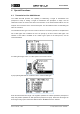
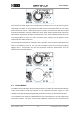
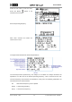
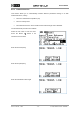
Enter the desired operating frequency
Enter the desired scan limit
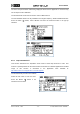
After some seconds the results are
shown on the screen.
The figure below describes the measured parameters:
Fop: operating frequency and measured
impedance at this frequency
Fra: resonant frequency and measured
impedance at this frequency
Calculated impedance at Fop
Ra: series resistance at Fop
Quality factor
Entry number in the file
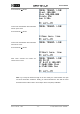
File name
Ca: antenna capacitance
La: antenna
inductance @ 1 MHz
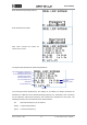
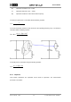
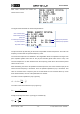
The internal procedure performed by the analyzer is as follows: the analyzer measures the
impedance at 1 MHz and at the desired operating frequency (e.g. 13.56 MHz). Then it searches
for the antenna’s self-resonant frequency and measures the impedance at that point. The
following parameters are extracted from these measurements:
Fra
Self-resonant frequency of the antenna
Z(Fop)
Z at operating frequency
Z(Fra)
Z at resonant frequency