HC-12 WIRELESS RF UART COMMUNICATION MODULE V2.4 USER MANUAL Version HC-12V2.
HC‐12 WIRELESS RF UART COMMUNICATION MODULE V2.4 USER MANUAL Specifications Long communication distance(About 1000 meters at default setting) Operating frequency range(433.4—473.0MHz) Transmit power(max: 20dBm) Power supply voltage(DC 3.2V ~5.5V) Product introduction HC-12 wireless RF UART communication module is a new generation of multi channel embedded wireless data transmission module. Radio frequency of 433.4 - 473.0MHz, can be setting communication channel, step is 400kHz, a total of 100 channel.
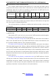
HC‐12 WIRELESS RF UART COMMUNICATION MODULE V2.4 USER MANUAL Pin definition The HC-12 module consists of 9 pins and a RF antenna block ANT1, which is defined as the following table: pin 1 definition I/O VCC explain Power pin, the requirements of 3.2V to 5.5V DC power supply, the supply current is not less than 200mA.(Note: If the module is to work for a long time in the transmit state, it is recommended that the power supply voltage of more than 4.
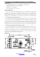
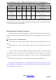
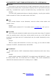
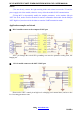
HC‐12 WIRELESS RF UART COMMUNICATION MODULE V2.4 USER MANUAL Wireless UART transmission ⑴ Brief introduction of the working principle As shown in the figure above, the HC-12 module is used to replace the physical connection in half duplex communication. On the left side of the device to send UART data to module, the module's RXD port after receiving the UART data, the data automatically transmitted to the air in the way of radio.
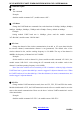
HC‐12 WIRELESS RF UART COMMUNICATION MODULE V2.4 USER MANUAL ⑶ The four kinds of UART transmission mode HC-12 module UART transmission mode default is FU3. At this point, the module works at full speed, the idle current is about 16mA.
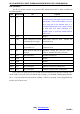
HC‐12 WIRELESS RF UART COMMUNICATION MODULE V2.4 USER MANUAL Here are some of the characteristics of the reference value of a variety of modes: mode FU1 FU2 FU3 FU4 note idle work current 3.
HC‐12 WIRELESS RF UART COMMUNICATION MODULE V2.4 USER MANUAL ⑵ Command explain ① AT Test command Example: Send the module command “AT”, module returns “OK”。 ② AT+Bxxxx Change the UART baud rate command. Can set the baud rate of 1200bps, 2400bps, 4800bps, 9600bps, 19200bps, 38400bps, 57600bps and 115200bps. Factory defaults to 9600bps. Example: Setting module UART baud rate is 19200bps, please send the module command "AT+B19200", module returns "OK+B19200".
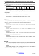
HC‐12 WIRELESS RF UART COMMUNICATION MODULE V2.4 USER MANUAL ⑤ AT+Px Set the transmit power level of the module, the x is 1-8, the module corresponding transmit power is as follows: x value 1 2 3 4 5 6 7 8 transmit power (dBm) -1 2 5 8 11 14 17 20 Default setting is 8,the transmit power is the biggest, the communication distance is the most distant. In general, the transmit power per drop 6~10dB, communication distance will be reduced by half.
HC‐12 WIRELESS RF UART COMMUNICATION MODULE V2.4 USER MANUAL ⑧ AT+Uxxx Set the data bits, parity bits and stop bits of UART communication. In the parity check bit, N represents the non parity check, O represents the odd parity check, E represents the even parity check. Stop, 1 on behalf of the 1 stop bit, 2 on behalf of the 2 stop, 3 on behalf of the 1.5 stop bit.
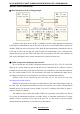
HC‐12 WIRELESS RF UART COMMUNICATION MODULE V2.4 USER MANUAL NOTE ①Do not directly connect the light emitting diode and resistor between the TX and the power supply side of the module, otherwise it may affect the module UART communication. ②Using MCU to dynamically modify the module parameters, set the module fifth pin "SET" low level, need to wait for the 40ms to send AT command to the module. Set the fifth pin "SET" high level, need to wait for the 80ms to enter the UART transmission mode.