
Data Sheet

Page 20
RFM95/96/97/98
Tel: +86-755-82973805 Fax: +86-755-82973550 E-mail: sales@hoperf.com http://www.hoperf.com
WIRELESS & SENSING PRELIMINARY DATASHEET
3. RFM95/96/97/98
Features
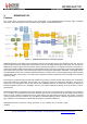
This section gives a high-level overview of the functionality of the RFM95/96/97/98 low-power, highly integrated
transceiver. The following figure shows a simplified block diagram of the RFM95/96/97/98.
Figure 3. RFM95/96/97/98 Block Schematic Diagram
RFM95/96/97/98 is a half-duplex, low-IF transceiver. Here the received RF signal is first amplified by the LNA. The LNA
inputs are single ended to minimise the external BoM and for ease of design. Following the LNA inputs, the conversion to
differential is made to improve the second order linearity and harmonic rejection. The signal is then down-converted to in-
phase and quadrature (I&Q) components at the intermediate frequency (IF) by the mixer stage. A pair of sigma delta ADCs
then perform data conversion, with all subsequent signal processing and demodulation performed in the digital domain.
The digital state machine also controls the automatic frequency correction (AFC), received signal strength indicator (RSSI)
and automatic gain control (AGC). It also features the higher-level packet and protocol level functionality of the top level
sequencer (TLS).
The frequency synthesisers generate the local oscillator (LO) frequency for both receiver and transmitter, one covering the
lower UHF bands (up to 525 MHz), and the other one covering the upper UHF bands (from 860 MHz). The PLLs are
optimized for user-transparent low lock time and fast auto-calibrating operation. In transmission, frequency modulation is
performed digitally within the PLL bandwidth. The PLL also features optional pre-filtering of the bit stream to improve
spectral purity.
RFM95/96/97/98 feature three distinct RF power amplifiers. Two of those, connected to RFO_LF and RFO_HF, can deliver
up to +14 dBm, are unregulated for high power efficiency and can be connected directly to their respective RF receiver
inputs via a pair of passive components to form a single antenna port high efficiency transceiver. The third PA, connected
to the PA_BOOST pin and can deliver up to +20 dBm via a dedicated matching network. Unlike the high efficiency PAs, this
high- stability PA covers all frequency bands that the frequency synthesizer addresses.
RFM95/96/97/98 also include two timing references, an RC oscillator and a 32 MHz crystal
oscillator.