
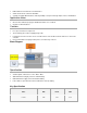
Data Sheet
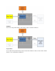

I
charge
(R
Iset
=2.0kΩ)
700mA
800mA
900mA
I
supply
0mA
600mA
V
batt
(R
x
=0Ω)
4.2V
V
source USB
5.0V
V
destination USB
5.0V
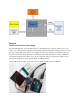
Pin definition and Rating
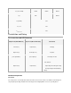
Pin Instruction and LED Statement
CH pin level(Red LED state)
OK pin level(Green LED state)
Statements
low level(on)
high level(off)
Charging
high level(off)
low level(last on)
Complete
pulse signal(flash)
pulse signal(on)
The battery isn't exist
high level(off)
high level(off)
Two situations :
Input voltage lower than gate voltage
The input voltage lower than battery
voltage
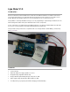
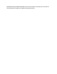
Hardware Components
Solar Panel
The solar panel is connectedto the board via the lower JST connector. Please note that the Solar Charger IC
only accepts input voltage inside the 4.8-6.0V range. If the charging LED is not on, it is possibly due to: