
Data Sheet
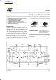
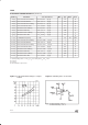
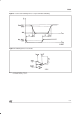
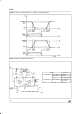
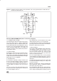
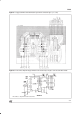

Figure 7 : For higher currents, outputscan be paralleled. Take care to parallel channel 1 with channel4
and channel2 with channel3.
APPLICATION INFORMATION (Refer to the block diagram)
1.1. POWER OUTPUT STAGE
TheL298integratestwopoweroutputstages(A; B).
The power output stage is a bridge configuration
and its outputs can drive an inductive load in com-
monor differenzialmode, dependingon thestate of
the inputs. The current that flows through the load
comes out from the bridge at the sense output : an
externalresistor (R
SA
;R
SB
.) allows todetect the in-
tensityof this current.
1.2. INPUT STAGE
Eachbridgeis driven by meansof fourgatesthe in-
put of which are In1 ; In2 ; EnA and In3 ; In4 ; EnB.
TheIninputsset thebridgestatewhenTheEn input
ishigh; a lowstateoftheEninputinhibitsthebridge.
All the inputs are TTL compatible.
2. SUGGESTIONS
A non inductive capacitor, usually of 100 nF, must
be foreseen between both Vs and Vss, to ground,
as near as possible toGND pin. Whenthe large ca-
pacitor of the power supply is too far from the IC, a
second smaller one must be foreseen near the
L298.
The sense resistor,not of a wire wound type, must
be groundednear the negativepole of Vs that must
be nearthe GND pin of the I.C.
Each input must be connectedto the source of the
driving signals by means of a very short path.
Turn-On and Turn-Off: Beforeto Turn-ONthe Sup-
plyVoltageand beforeto TurnitOFF,theEnablein-
put must be driven to the Low state.
3. APPLICATIONS
Fig 6 showsa bidirectionalDC motor controlSche-
maticDiagram forwhich only one bridge is needed.
The external bridge of diodes D1 to D4 is made by
four fast recovery elements (trr
≤ 200 nsec) that
must be chosen of a VF as low as possible at the
worst case of the load current.
The senseoutputvoltagecanbeusedto controlthe
current amplitude by chopping the inputs,or to pro-
vide overcurrent protectionby switchinglow theen-
able input.
The brake function (Fast motor stop) requires that
the Absolute Maximum Rating of 2 Amps must
neverbe overcome.
When the repetitive peak current needed from the
load is higher than 2 Amps,a paralleled configura-
tion can be chosen (See Fig.7).
An external bridge of diodes are required when in-
ductive loads are driven and when the inputsof the
ICare chopped; Shottkydiodeswouldbepreferred.
L298
7/13