
User Manual


User manual/ Technical information
© 2008-2020 Seeed Technology Co., Ltd. All rights reserved. www.seeed.cc
The 27 Page total 50
Modbus-RTU Protocol
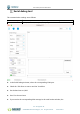
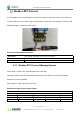
To start Modbus-RTU communication, the M12 data cable of the device needs to be connected
to the RS-485 port of one Data Logger, which powers up the device at a voltage of 12V-24V. The
following image is a diagram of the wiring:
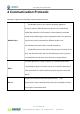
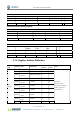
Protocol communication parameters
Data Format One start bit, 8 Data bits, None parity, one Stop bits.
Baud Rate 9600bps (default), which can be modified by configuration.
Default Device Address 0x01
4.1.1 Modbus-RTU Protocol Message Format
Sensor data is stored in the Input Register and is read-only
The device address and the communication baud rate of RS-485 are stored in the Holding
Register and can be modified.
Each register is 16bits and takes up 2 bytes.
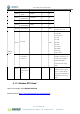
Read the message from the input register.
The message format from by the host
Slave address Function code Register address Number of registers CRC check
1 byte 1 byte 2 bytes (big-endian). 2 Byte (big-endian). 2 bytes
AA 0x04 RRRR NNNN CCCC
Address 0-247 0x04 big endian big endian little endian