
Data Sheet

ams Datasheet Page 33
[v1-06] 2018-Jun-20 Document Feedback
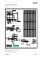
AS5600 − Application Information
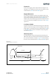
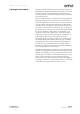
Figure 39:
Recommended External Components
Note(s):
1. Given parameter characteristics have to be fulfilled over operation temperature and product lifetime
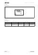
Magnetic Requirements
The AS5600 requires the magnetic field component Bz
perpendicular to the sensitive area on the chip.
Along the circumference of the Hall element circle the magnetic
field Bz should be sine-shaped. The magnetic field gradient of
Bz along the radius of the circle should be in the linear range
of the magnet to eliminate displacement error by the
differential measurement principle.
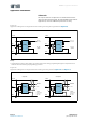
Figure 40:
Magnetic Field Bz and Typical Airgap
The typical airgap is between 0.5 mm and 3 mm, and it depends
on the selected magnet. A larger and stronger magnet allows a
larger airgap. Using the AGC value as a guide, the optimal airgap
can be found by adjusting the distance between the magnet
and the AS5600 so that the AGC value is in the center of its
range. The maximum allowed displacement of the rotational
axis of the reference magnet from the center of the package is
0.25 mm when using a magnet with a diameter of 6mm.
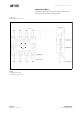
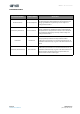
Component Symbol Value Units Notes
VDD5V buffer capacitor C1 100 nF 20%
LDO regulator capacitor C2 1 μF 20%; < 100 mΩ; Low ESR ceramic capacitor
Optional pull-up for I²C bus RPU 4.7 KΩ Refer to UM10204 for RPU sizing
0.5 – 3 mm typ.
S
N