
Data Sheet


ams Datasheet Page 27
[v1-06] 2018-Jun-20 Document Feedback
AS5600 − Register Description
PWM Output Mode
The AS5600 output stage can be programmed in the OUTS bits
of the CONF register for a PWM-encoded digital output (OUTS
= 10). In this mode, the OUT pin provides a digital PWM signal.
The duty cycle of each pulse is proportional to the absolute
angle of the rotating magnet.
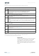
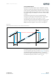
The PWM signal consists of a frame of 4351 PWM clock periods
as shown in Figure 30. This PWM frame is composed of the
following sections:
• 128 PWM clock periods high
• 4095 PWM clock periods data
• 128 PWM clock periods low
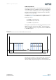
The angle is represented in the data part of the frame, and one
PWM clock period represents one 4096
th
of the full angular
range. The PWM frequency is programmed with the PWMF bits
in the CONF register.
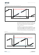
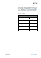
Figure 30:
Output Characteristics in Pulse Width Modulation Mode
An angle of zero degrees is represented by 128 clock periods
high and 4223 clock periods low, while a maximum angle
consists of 4223 clock periods high and 128 clock periods low.
time
1
2
3
4
5
6
7
8
4095
4094
4093
4092
4091
4090
4089
4088
4087
4086
4085
data
128 c lock
periods low
128 clock
periods high
9