
Data Sheet


ams Datasheet Page 23
[v1-06] 2018-Jun-20 Document Feedback
AS5600 − Register Description
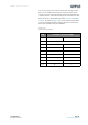
Figure 25:
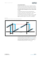
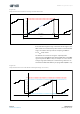
Option B: Angle Programming Through the OUT Pin
Note(s):
1. After step 5 the new setting is effective at the output.
2. If step 3 is not followed by step 5 no permanent write will be performed.
3. It is highly recommended to perform a functional test after the procedure.
4. This procedure can be executed only one time; the zero position and maximum angle can be reprogrammed only through the I²C
(Option A).
5. This procedure can be executed only if the presence of the magnet is detected (MD = 1).
Use the correct hardware configuration shown in Figure 37 and Figure 38. The PGO pin is connected to GND
and the OUT pin is pulled high by an internal resistor until the programming procedure is finished.
Step 1 Power up the AS5600.
Step 2 Position the magnet in the start position.
Step 3 Pull the OUT pin to GND for at least 100 ms, then allow the pin to float.
Step 4
Rotate the magnet in the same direction defined by the level on the DIR pin (GND for clockwise,
VDD for counterclockwise) to the stop position. The amount of rotation must be greater than
18 degrees.
Step 5 Pull the OUT pin to GND for at least 100 ms, then allow the pin to float.
Step 6
Check if the OUT pin is permanently driven to GND. This indicates an error occurred during
programming. If the voltage driven on the OUT pin corresponds to the magnet position, the
procedure was performed successfully.