
Data Sheet


Page 22 ams Datasheet
Document Feedback [v1-06] 2018-Jun-20
AS5600 − Register Description
There are three recommended methods for programming the
angular range:
• Option A: Angle Programming Through the I²C Interface
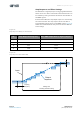
• Option B: Angle Programming Through the OUT Pin
•Option C: Programming a Maximum Angular Range
Through the I²C Interface
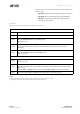
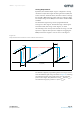
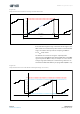
Figure 24:
Option A: Angle Programming Through the I²C Interface
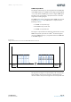
Note(s):
1. After each register command, the new setting is effective at the output at least 1 ms later.
2. It is highly recommended to perform a functional test after this procedure.
Use the correct hardware configuration shown in Figure 37 and Figure 38.
Step 1 Power up the AS5600.
Step 2 Turn the magnet to the start position.
Step 3
Read the RAW ANGLE register.
Write the RAW ANGLE value into the ZPOS register.
Wait at least 1 ms.
Step 4
Rotate the magnet in the direction defined by the level on the DIR pin (GND for clockwise, VDD
for counterclockwise) to the stop position. The amount of rotation must be greater than
18 degrees.
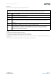
Step 5
Read the RAW ANGLE register.
Write the RAW ANGLE value into the MPOS register.
Wait at least 1 ms.
Proceed with Step 6 to permanently program the configuration.
Step 6
Perform a BURN_ANGLE command to permanently program the device.
Wait at least 1 ms.
Step 7
Verify the BURN_ANGLE command:
Write the commands 0x01, 0x11 and 0x10 sequentially into the register 0xFF to load the actual
OTP content.
Read the ZPOS and MPOS registers to verify that the BURN_ANGLE command was successful.
Step 8 Read and verify the ZPOS and MPOS registers again after a new power-up cycle.