
Data Sheet

Page 20 ams Datasheet
Document Feedback [v1-06] 2018-Jun-20
AS5600 − Register Description
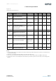
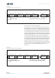
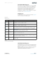
STATUS Register
The STATUS register provides bits that indicate the current state
of the AS5600.
Figure 23:
STATUS Register
AGC Register
The AS5600 uses Automatic Gain Control in a closed loop to
compensate for variations of the magnetic field strength due
to changes of temperature, airgap between IC and magnet, and
magnet degradation. The AGC register indicates the gain. For
the most robust performance, the gain value should be in the
center of its range. The airgap of the physical system can be
adjusted to achieve this value.
In 5V operation, the AGC range is 0-255 counts. The AGC range
is reduced to 0-128 counts in 3.3V mode.
MAGNITUDE Register
The MAGNITUDE register indicates the magnitude value of the
internal CORDIC.
Non-Volatile Memory (OTP)
The non-volatile memory is used to permanently program the
configuration. To program the non-volatile memory, the I²C
interface is used (Option A, Option C). Alternatively, start and
stop positions can be programmed through the output pin
(Option B). The programming can be either performed in the
5V supply mode or in the 3.3V operation mode but using a
minimum supply voltage of 3.3V and a 10 μF capacitor at the
VDD3V3 pin to ground. This 10 μF capacitor is needed only
during the programming of the device. Two different
commands are used to permanently program the device:
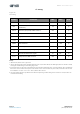
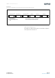
Name State When Bit Is High
MH AGC minimum gain overflow, magnet too strong
ML AGC maximum gain overflow, magnet too weak
MD Magnet was detected