
Data Sheet

Page 18 ams Datasheet
Document Feedback [v1-06] 2018-Jun-20
AS5600 − Register Description
The following registers are accessible over the serial I²C
interface. The 7-bit device address of the slave is 0x36
(0110110 in binary). To permanently program a configuration,
a non-volatile memory (OTP) is provided.
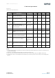
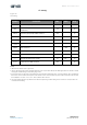
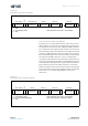
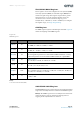
Figure 21:
Register Map
Note(s):
1. To change a configuration, read out the register, modify only the desired bits and write the new configuration. Blank fields may
contain factory settings.
2. During power-up, configuration registers are reset to the permanently programmed value. Not programmed bits are zero.
Address Name R/W Bit 7 Bit 6 Bit 5 Bit 4 Bit 3 Bit 2 Bit 1 Bit 0
Configuration Registers
(1),
(2)
0x00 ZMCO RZMCO(1:0)
0x01
ZPOS R/W/P
ZPOS(11:8)
0x02 ZPOS(7:0)
0x03
MPOS R/W/P
MPOS(11:8)
0x04 MPOS(7:0)
0x05
MANG R/W/P
MANG(11:8)
0x06 MANG(7:0)
0x07
CONF R/W/P
WD FTH(2:0) SF(1:0)
0x08 PWMF(1:0) OUTS(1:0) HYST(1:0) PM(1:0)
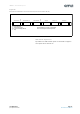
Output Registers
0x0C
RAW
ANGLE
RRAW ANGLE(11:8)
0x0D R RAW ANGLE(7:0)
0x0E
ANGLE
R ANGLE(11:8)
0x0F R ANGLE(7:0)
Status Registers
0x0B STATUS RMDMLMH
0x1A AGC RAGC(7:0)
0x1B
MAGNITUDE
R MAGNITUDE (11:8)
0x1C R MAGNITUDE(7:0)
Burn Commands
0xFF BURN W Burn_Angle = 0x80; Burn_Setting = 0x40
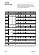
Register Description