
Data Sheet

Page 16 ams Datasheet
Document Feedback [v1-06] 2018-Jun-20
AS5600 − Detailed Description
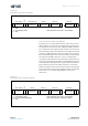
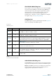
Figure 18:
Data Write (Slave Receiver Mode)
Slave Transmitter Mode (Read Mode)
The first byte is received and handled as in the slave receiver
mode. However, in this mode, the direction bit indicates that
the AS5600 will drive data on SDA. START and STOP conditions
are recognized as the beginning and end of a bus transaction.
The slave address byte is the first byte received after the master
generates a START condition. The slave address byte contains
the 7-bit AS5600 address. The 7-bit slave address is followed by
the direction bit (R/W), which, for a read, is 1 (high). After
receiving and decoding the slave address byte, the slave device
drives an acknowledge on the SDA line. The AS5600 then begins
to transmit data starting with the register address pointed to
by the address pointer. If the address pointer is not written
before the initiation of a read transaction, the first address that
is read is the last one stored in the address pointer. The AS5600
must receive a not acknowledge (NACK) to end a read
transaction.
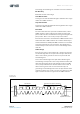
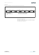
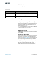
Figure 19:
Data Read (Slave Transmitter Mode)
S 0110110 0 A XXXXXXXX A XXXXXXXX A XXXXXXXX A
S – Start
A – Acknowledge (ACK) Data transferred: X+1 Bytes + Acknowledge
P – Stop
P
<Slave address> <Word address (n)> <Data(n)> <Data(n+X)>
<RW>
XXXXXXXX A
<Data(n+1)>
S 0110110 1 A XXXXXXXX A XXXXXXXX A XXXXXXXX NA
S – Start
A – Acknowledge (ACK) Data transferred: X+1 Bytes + Acknowledge
NA – Not Acknowledge (NACK) Note: Last data byte is followed by NACK
P – Stop
P
<Slave address> <Data(n)> <Data(n+1)> <Data(n+X)>
<RW>
XXXXXXXX A
<Data(n+2)>