
Data Sheet

Page 12 ams Datasheet
Document Feedback [v1-06] 2018-Jun-20
AS5600 − Detailed Description
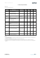
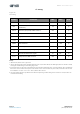
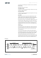
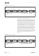
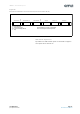
I²C Timing
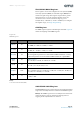
Figure 16:
I²C Timing
Note(s):
1. After this time, the first clock is generated.
2. A device must internally provide a minimum hold time of 120 ns (Fast-mode Plus) for the SDA signal (referred to the V
IHmin
of SCL)
to bridge the undefined region of the falling edge of SCL.
3. A Fast-mode device can be used in a standard-mode system, but the requirement t
SU;DAT
= 250 ns must be met. This is automatically
if the device does not stretch the low phase of SCL. If such a device does stretch the low phase of SCL, it must drive the next data
bit on SDA (t
Rmax
+ t
SU;DAT
= 1000 + 250 = 1250 ns) before SCL is released.
4. In Fast-mode Plus, fall time is specified the same for both output stage and bus timing. If series resistors are used, this has to be
considered for bus timing.
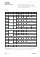
Symbol Parameter Min Max Unit
f
SCLK
SCL clock frequency 1.0 MHz
t
BUF
Bus free time (time between the STOP and START
conditions)
0.5 μs
t
HD;STA
Hold time; (Repeated) START condition
(1)
0.26 μs
t
LOW
Low phase of SCL clock 0.5 μs
t
HIGH
High phase of SCL clock 0.26 μs
t
SU;STA
Setup time for a Repeated START condition 0.26 μs
t
HD;DAT
Data hold time
(2)
0.45 μs
t
SU;DAT
Data setup time
(3)
50 ns
t
R
Rise time of SDA and SCL signals 120 ns
t
F
Fall time of SDA and SCL signals 10
120
(4)
ns
t
SU;STO
Setup time for STOP condition 0.26 μs