
Data Sheet

ams Datasheet Page 11
[v1-06] 2018-Jun-20 Document Feedback
AS5600 − Detailed Description
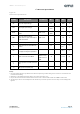
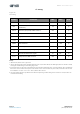
I²C Electrical Specification
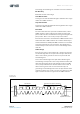
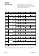
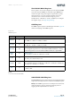
Figure 15:
I²C Electrical Specifications
Note(s):
1. In Fast-mode Plus, fall time is specified the same for both output stage and bus timing. If series resistors are used this has to be
considered for bus timing.
2. Input filters on the SDA and SCL inputs suppress noise spikes of less than 50 ns.
3. I/O pins of Fast-mode and Fast-mode Plus devices must not load or drive the SDA and SCL lines if VDD is switched OFF.
4. Special-purpose devices such as multiplexers and switches may exceed this capacitance because they connect multiple paths
together.
Symbol Parameter Conditions Min Typ Max Unit
VIL Logic low input voltage -0.3
0.3 x
VDD
V
VIH Logic high input voltage
0.7 x
VDD
VDD +
0.3
V
VHYS
Hysteresis of Schmitt trigger
inputs
VDD > 2.5V
0.05 x
VDD
V
VOL
Logic low output voltage
(open-drain or open-collector) at
3 mA sink current
VDD > 2.5V 0.4 V
IOL Logic low output current VOL = 0.4V 20 mA
t
OF
Output fall time from VIHmax to
VILmax
10
120
(1)
ns
t
SP
Pulse width of spikes that must
be suppressed by the input filter
50
(2)
ns
I
I
Input current at each I/O Pin
Input Voltage
between 0.1 x
VDD and 0.9 x
VDD
-10
+10
(3)
μA
C
B
Total capacitive load for each bus
line
550 pF
C
I/O
I/O capacitance (SDA, SCL)
(4)
10 pF