
Data Sheet

Page 10 ams Datasheet
Document Feedback [v1-06] 2018-Jun-20
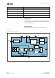
AS5600 − Detailed Description
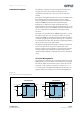
I²C Interface
The AS5600 supports the 2-wire Fast-mode Plus I²C-slave
protocol in device mode, in compliance with the NXP
Semiconductors (formerly Philips Semiconductors)
specification UM10204. A device that sends data onto the bus
is a transmitter and a device receiving data is a receiver. The
device that controls the message is called a master. The devices
that are controlled by the master are called slaves. A master
device generates the serial clock (SCL), controls the bus access,
and generates the START and STOP conditions that control the
bus. The AS5600 always operates as a slave on the I²C bus.
Connections to the bus are made through the open-drain I/O
lines SDA and the input SCL. Clock stretching is not included.
The host MCU (master) initiates data transfers. The 7-bit slave
address of the AS5600 is 0x36 (0110110 in binary).
Supported Modes
• Random/Sequential read
• Byte/Page write
• Automatic increment (ANGLE register)
• Standard-mode
• Fast-mode
• Fast–mode plus
The SDA signal is the bidirectional data line. The SCL signal is
the clock generated by the I²C bus master to synchronize
sampling data from SDA. The maximum SCL frequency is 1 MHz.
Data is sampled on the rising edge of SCL.
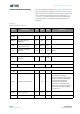
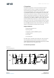
I²C Interface Operation
Figure 14:
I²C Timing Diagram
SDA
SCL
Start
Stop
t
buf
t
LOW
t
R
t
HD.STA
t
HIGH
t
F
t
SU.DAT
t
SU.STA
t
HD.STA
t
SU.STO
Repeated
Start
t
HD.DAT