
Data Sheet

- 5 -
Aosong Guangzhou Electronics Co., Ltd. Order by phone:4006 305378 Enterprise QQ:4006305378 www.aosong.com
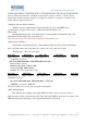
Data Timing Diagram
Note: The host reads temperature and humidity data from DHT11 always previous
measurements, such as the two measured time interval is long, please read twice in a row is the
second time in real time temperature and humidity values.
◎Peripheral reading step
Communication between master and slave can be completed by the following steps (peripherals
(such as a microprocessor) to read step DHT11 data).
Step one:
DHT11 after power (power after DHT11 1S to wait to cross the unstable state during this period
can’t send any commands), test environment temperature and humidity data, and record data while
the data lines DATA DHT11 pulled by a pull-up resistor remains high; DHT11 this time the DATA
pin is the input state, always detect external signals.
Step two:
Microprocessor I / O output while the output is set to low, and low retention time can’t be less
than 18ms, then the microprocessor I / O is set to enter the state, due to the pull-up resistor, the
microprocessor I / O that the data lines DHT11 also will go high, waiting to answer DHT11 signals
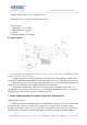
transmitted signal as shown:
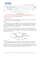
The host sends a start signal
Step three:
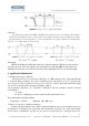
DHT11 the DATA pin when external signals detected low, waiting for the external signal low
end, after a delay DHT11 the DATA pin is an output, the output low as 80 microseconds response
signal, followed by the output of 80 micro-notify the second high peripheral is ready to receive data,
the microprocessor I / O at this time in the input state detecting I / O with low (DHT11 echo signal)
to the wait for 80 microseconds high data receiving and sending signals as shown: