
Datasheet


REF: BBONEGRN_SRM BeagleBone Green
System Reference Manual Rev V1a
19
numerous sources. A 1A supply is sufficient to power the board, but if there is a cape
plugged into the board or you have a power hungry device or hub plugged into the host
port, then more current may needed from the P9 Expansion connector VDD_5V pin.
Power routed to the board via the expansion header could be provided from power
derived on a cape.
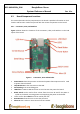
5.9 Reset Button
When pressed and released, causes a reset of the board. The reset button used on the
BeagleBone Black is a little larger than the one used on the original BeagleBone. It has also
been moved out to the edge of the board so that it is more accessible.
5.10 Power Button
A power button is provided near the reset button close to the Ethernet connector. This
button takes advantage of the input to the PMIC for power down features. While a lot of
capes have a button, it was decided to add this feature to the board to ensure everyone
had access to some new features. These features include:
Interrupt is sent to the processor to facilitate an orderly shutdown to save files and
to un-mount drives.
Provides ability to let processor put board into a sleep mode to save power.
Can alert processor to wake up from sleep mode and restore state before sleep was
entered.
If you hold the button down longer than 8 seconds, the board will power off if you release
the button when the power LED turns off. If you continue to hold it, the board will power
back up completing a power cycle.
We recommend that you use this method to power down the board. It will also help
prevent contamination of the SD card or the eMMC.
If you do not remove the power jack, you can press the button again and the board will
power up.
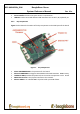
5.11 Indicators
There are a total of five blue LEDs on the board.
One blue power LED indicates that power is applied and the power management IC
is up. If this LED flashes when applying power, it means that an excess current flow
was detected and the PMIC has shut down.