
Datasheet


REF: BBONEGRN_SRM BeagleBone Green
System Reference Manual Rev V1a
13
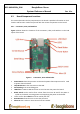
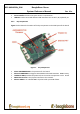
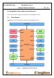
4.3 Board Component Locations
This section describes the key components on the board. It provides information on their
location and function. Familiarize yourself with the various components on the board.
4.3.1 Connectors, LEDs, and Switches
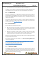
Figure 6 below shows the locations of the connectors, LEDs, and switches on the PCB
layout of the board.
Figure 6. Connectors, LEDs and Switches
Power Button alerts the processor to initiate the power down sequence and is used
to power down the board.
10/100 Ethernet is the connection to the LAN.
Serial Debug is the serial debug port.
USB Client is a Micro USB connection to a PC that can also power the board.
BOOT switch can be used to force a boot from the micro SD card if the power is
cycled on the board, removing power and reapplying the power to the board.
There are four blue LEDS that can be used by the user.
Reset Button allows the user to reset the processor.
Micro SD slot is where a micro SD card can be installed.