REF: BBONEGRN_SRM BeagleBone Green System Reference Manual BeagleBone Green System Reference Manual Revision v1 Oct 9, 2015 Reference to the BBB_SRM 1 Rev V1a
REF: BBONEGRN_SRM BeagleBone Green System Reference Manual Rev V1a THIS DOCUMENT This work is licensed under the Creative Commons Attribution-Share Alike 3.0 Unported License. To view a copy of this license, visit http://creativecommons.org/licenses/bysa/3.0/ or send a letter to Creative Commons, 171 Second Street, Suite 300, San Francisco, California, 94105, USA. All derivative works are to be attributed to Gerald Coley of BeagleBoard.org. For more information, see http://creativecommons.
REF: BBONEGRN_SRM BeagleBone Green System Reference Manual Rev V1a BEAGLEBONE DESIGN These design materials referred to in this document are *NOT SUPPORTED* and DO NOT constitute a reference design. Only “community” support is allowed via resources at BeagleBoard.org/discuss. THERE IS NO WARRANTY FOR THE DESIGN MATERIALS, TO THE EXTENT PERMITTED BY APPLICABLE LAW.
REF: BBONEGRN_SRM BeagleBone Green System Reference Manual Rev V1a Table of Contents 1.0 Introduction 6 2.0 Change History 6 2.1 Document Change History ................................................................................ 6 3.0 Connecting Up Your BeagleBone Green 3.1 What’s In the Box .......................................................................................... 7 3.2 Main Connection Scenarios ........................................................................... 8 3.
REF: BBONEGRN_SRM BeagleBone Green System Reference Manual Rev V1a 5.11 Indicators ................................................................................................. 19 5.12 CTI JTAG Header .......................................................................................... 20 5.13 Grove Interfaces.......................................................................................... 20 5.14 Cape Board Support ................................................................
REF: BBONEGRN_SRM BeagleBone Green Rev V1a System Reference Manual 1.0 Introduction This document is the System Reference Manual for the BeagleBone Green and covers its use and design. The board will primarily be referred to in the remainder of this document simply as the board, although it may also be referred to as the BeagleBone Green as a reminder. There are also references to the original BeagleBone as well, and will be referenced as simply BeagleBone.
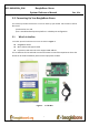
REF: BBONEGRN_SRM BeagleBone Green System Reference Manual Rev V1a 3.0 Connecting Up Your BeagleBone Green This section provides instructions on how to hook up your board. Two scenarios will be discussed: 1) Tethered to a PC and 2) As a standalone development platform in a desktop PC configuration. 3.1 What’s In the Box In the box you will find three main items as shown in Figure 1. BeagleBone Green Micro USB to USB Type A Cable Instruction card with link to the support WIKI address.
REF: BBONEGRN_SRM BeagleBone Green System Reference Manual 3.2 Rev V1a Main Connection Scenarios This section will describe how to connect the board for use. This section is basically a slightly more detailed description of the Quick Start Guide that came in the box. There is also a Quick Start Guide document on the board that should also be referred to.
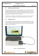
REF: BBONEGRN_SRM BeagleBone Green System Reference Manual Rev V1a All the power for the board is provided by the PC via the USB cable. In some instances, the PC may not be able to supply sufficient power for the board. In that case, an external 5VDC power supply can be used to power the board through VDD_5V pin in P9 connector, but this should rarely be necessary. 3.3.1 Connect the Cable to the Board 1. Connect the small connector on the USB cable to the board as shown in Figure 4.
REF: BBONEGRN_SRM BeagleBone Green System Reference Manual Figure 4. Rev V1a Board Power LED 4. When the board starts to the booting process started by the process of applying power, the LEDs will come on in sequence as shown in Figure 5 below. It will take a few seconds for the status LEDs to come on, so be patient. The LEDs will be flashing in an erratic manner as it begins to boot the Linux kernel. Figure 5.
REF: BBONEGRN_SRM BeagleBone Green System Reference Manual Rev V1a 3.3.2 Accessing the Board as a Storage Drive The board will appear around a USB Storage drive on your PC after the kernel has booted, which will take a round 10 seconds. The kernel on the board needs to boot before the port gets enumerated. Once the board appears as a storage drive, do the following: 1) Open the USB Drive folder. 2) Click on the file named start.
REF: BBONEGRN_SRM BeagleBone Green System Reference Manual 4.2 Rev V1a BeagleBone Green Features and Specification Table 2. BeagleBone Green Features Feature Processor Sitara AM3358BZCZ100 1GHz, 2000 MIPS Graphics Engine SGX530 3D, 20M Polygons/S 512MB DDR3L 800MHZ SDRAM Memory Onboard Flash 4GB, 8bit Embedded MMC Power Source Micro USB Jack,5VDC External Via Expansion Header PCB 3.4” x 2.1” , 6 layers Indicators 1-Power, 2-Ethernet, 4-User Controllable LEDs HS USB 2.
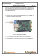
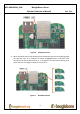
REF: BBONEGRN_SRM BeagleBone Green System Reference Manual 4.3 Rev V1a Board Component Locations This section describes the key components on the board. It provides information on their location and function. Familiarize yourself with the various components on the board. 4.3.1 Connectors, LEDs, and Switches Figure 6 below shows the locations of the connectors, LEDs, and switches on the PCB layout of the board. Figure 6.
REF: BBONEGRN_SRM BeagleBone Green System Reference Manual Rev V1a Grove Interface is where the Grove sensor is connected to. USB Host can be connected different USB interfaces such as Wi-Fi, BT, Keyboard, etc. 4.3.2 Key Components Figure 7 below shows the locations of the key components on the PCB layout of the board. Figure 7. Key Components Sitara AM3358BZCZ100 is the processor for the board. Micron 512MB DDR3L or Kingston 512mB DDR3 is the Dual Data Rate RAM memory.
REF: BBONEGRN_SRM BeagleBone Green System Reference Manual 5.0 BeagleBone Green High Level Specification This section provides the high level specification of the BeagleBone Green. 5.1 Block Diagram Figure 8 below is the high level block diagram of the BeagleBone Green. Figure 8.
REF: BBONEGRN_SRM BeagleBone Green System Reference Manual 5.2 Rev V1a Processor Sitara AM3358BZCZ100 5.3 Memory Described in the following sections are the three memory devices found on the board. 5.3.1 512MB DDR3L A single 256Mb x16 DDR3L 4Gb (512MB) memory device is used. The memory used is is one of two devices: - MT41K256M16HA-125 from Micron - D2516EC4BXGGB from Kingston It will operate at a clock frequency of 400MHz yielding an effective rate of 800MHZ on the DDR3L bus allowing for 1.
REF: BBONEGRN_SRM BeagleBone Green System Reference Manual Rev V1a with the board. Booting from MMC0 will be used to flash the eMMC in the production environment or can be used by the user to update the SW as needed. 5.3.5 Boot Modes As mentioned earlier, there are four boot modes: eMMC Boot...
REF: BBONEGRN_SRM BeagleBone Green System Reference Manual Rev V1a DDR3L requires 1.5V instead of 1.8V on the DDR2 as is the case on the original BeagleBone. The 1.8V regulator setting has been changed to 1.5V for the DDR3L. The LDO3 3.3V rail has been changed to 1.8V to support those rails on the processor. LDO4 is still 3.3V for the 3.3V rails on the processor. An external LDOTLV70233 provides the 3.3V rail for the rest of the board. 5.
REF: BBONEGRN_SRM BeagleBone Green System Reference Manual Rev V1a numerous sources. A 1A supply is sufficient to power the board, but if there is a cape plugged into the board or you have a power hungry device or hub plugged into the host port, then more current may needed from the P9 Expansion connector VDD_5V pin. Power routed to the board via the expansion header could be provided from power derived on a cape. 5.9 Reset Button When pressed and released, causes a reset of the board.
REF: BBONEGRN_SRM BeagleBone Green System Reference Manual Rev V1a Four blue LEDs that can be controlled via the SW by setting GPIO pins. In addition, there are two LEDs on the RJ45 to provide Ethernet status indication. One is yellow (100M Link up if on) and the other is green (Indicating traffic when flashing). 5.12 CTI JTAG Header A place for an optional 20 pin CTI JTAG header is provided on the board to facilitate the SW development and debugging of the board by using various JTAG emulators.
REF: BBONEGRN_SRM BeagleBone Green System Reference Manual Rev V1a The majority of capes designed for the original BeagleBone or BeagleBone Black will work on the BeagleBone Green. The two main expansion headers will be populated on the board. There are a few exceptions where certain capabilities may not be present or are limited to the BeagleBone Green. These include: GPMC bus may NOT be available due to the use of those signals by the eMMC.
REF: BBONEGRN_SRM BeagleBone Green System Reference Manual 6.0 BeagleBone Green Mechanical 6.1 Dimensions and Weight Size: Max height: PCB Layers: PCB thickness: RoHS Compliant: 3.5” x 2.15” (86.36mm x 53.34mm) .187” (4.76mm) 6 .062” Yes 1.
REF: BBONEGRN_SRM BeagleBone Green System Reference Manual 6.2 Board Dimensions Figure 9.
REF: BBONEGRN_SRM BeagleBone Green System Reference Manual 7.0 Pictures Figure 10.
REF: BBONEGRN_SRM BeagleBone Green System Reference Manual Figure 11.
REF: BBONEGRN_SRM BeagleBone Green System Reference Manual 8.0 Rev V1a Support Information All support for this design is through the BeagleBoard.org community at: beagleboard@googlegroups.com or http://beagleboard.org/discuss. 8.1 Hardware Design Design documentation can be found on the eMMC of the board under the documents/hardware directory when connected using the USB cable. Provided there is: Schematic in PDF Schematic in OrCAD (Cadence Design Entry CIS 16.