
Datasheet


www.sensirion.com Version 0.9 – August 2017 10/15
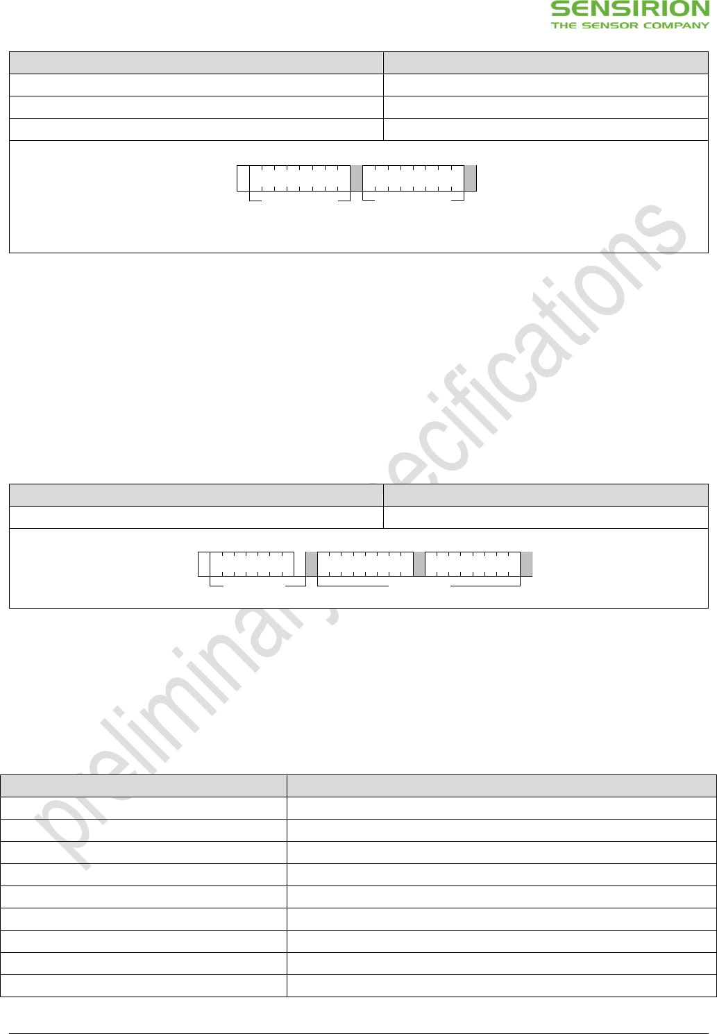
Command
Hex. Code
Address byte
0x00
Second byte
0x06
Reset Command using the General Call address
0x0006
Table 11 Reset through the General Call address (Clear blocks are controlled by the microcontroller, grey blocks by the sensor.).
6.5 Get Serial ID
The readout of the serial ID register can be used to identify the chip and verify the presence of the sensor. The appropriate
command structure is shown in Table 12. After issuing the measurement command and sending the ACK Bit the sensor
needs the time t
IDLE
= 0.5ms to respond to the I
2
C read header with an ACK Bit. Hence, it is recommended to wait t
IDLE
=0.5ms
before issuing the read header.
The get serial ID command returns 3 words, and every word is followed by an 8-bit CRC checksum. Together the 3 words
constitute a unique serial ID with a length of 48 bits.
The ID returned with this command are represented in the big endian (or MSB first) format.
Command
Hex. Code
Get Serial ID
0x3682
Table 12 Get serial ID command.
6.6 Checksum Calculation
The 8-bit CRC checksum transmitted after each data word is generated by a CRC algorithm. Its properties are displayed in
Table 13. The CRC covers the contents of the two previously transmitted data bytes. To calculate the checksum only these
two previously transmitted data bytes are used.
Property
Value
Name
CRC-8
Width
8 bit
Protected Data
read and/or write data
Polynomial
0x31 (x8 + x5 + x4 + 1)
Initialization
0xFF
Reflect input
False
Reflect output
False
Final XOR
0x00
Examples
CRC (0xBEEF) = 0x92
Table 13 I
2
C CRC properties.
S
ACK
General Call Address
1 2 3 4 5 6 7 8 9
ACK
Reset Command
1 2 3 4 5 6 7 8 9
General Call 1
st
byte
General Call 2
nd
byte
S
ACK
W
I2C Address
1 2 3 4 5 6 7 8 9
ACK
Command MSB
1 2 3 4 5 6 7 8 9
ACK
Command LSB
10 11 12 13 14 15 16 17 18
16-bit command
I2C write header