
User Manual


Page.27.
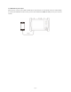
Connect a network cable from a PoE switch to the IP BUDDY+’s PSE IN port. Connect an IP camera or other PoE using
node to IP BUDDY+’s LAN port, the PoE voltage and the cable’s pin connection status show on the screen.
Note:This test if for measuring the voltage being drawn by the PoE node and the IP BUDDY+ must be
between the PoE switch and the PoE node for this test to work.
Note: The PoE switch must be connected to the PSE IN port. The powered device such as IP camera or other
PoE node must be connected to the LAN port.
Note: Do not connect PoE power supply equipment (such as a PoE switch) to the tester’s UTP/SCAN port;
otherwise it will damage the tester.
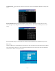
3.3.15 Calculator
Click the icon to open the Calculator app.
3.3.16 Browser
Click the icon to open the Browser app.
Type in the camera’s IP address and press “Go” to access the IP camera’s interface.
NOTE: You will not be able to view live video in the web browser. For viewing video, use the IP BUDDY+ live camera view
apps.
The IP camera and IP Buddy+ must be on the same network segment for the browser to interface with the camera. If they
are not in the same segment, click the button or press “RETRUN” to exit. Open the “Settings” app from the main menu
to change the IP Buddy+’s network settings to match those of the IP camera.