SecurityMan® Network Edition 4CH Triplex Digital Video Recorder SecurityMan ® User's Manual NDVR-04
Copyright 2 © Copyright 2005 This manual is furnished under license and may be used or copied only in accordance with the terms of such license. Except as permitted by such license, no part of this publication may be reproduced, stored in a retrieval system, or transmitted, in any form or any means, electronic, mechanical, recording, or otherwise, including translation to another language or format, without the prior written permission of Part.
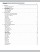
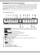
Contents 1 3 Introduction . . . . . . . . . . . . . . . . . . . . . . . . . . . . . . . . . . . . . . . . . . . . . . . . . . . . . . . . . . . . . . . 5 Front Panel Key Function . . . . . . . . . . . . . . . . . . . . . . . . . . . . . . . . . . . . . . . . . . . . . . . . . . . 5 Rear Panel Function . . . . . . . . . . . . . . . . . . . . . . . . . . . . . . . . . . . . . . . . . . . . . . . . . . . . . . . 6 2 DVR Installation . . . . . . . . . . . . . . . . . . . . . . . . . . . . . . . . . . . . . .
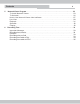
Contents 5 4 Network Viewer Program . . . . . . . . . . . . . . . . . . . . . . . . . . . . . . . . . . . . . . . . . . . . . . . . . . . 23 To Install Network Viewer. . . . . . . . . . . . . . . . . . . . . . . . . . . . . . . . . . . . . . . . . . . . . . . . . 23 To Uninstall . . . . . . . . . . . . . . . . . . . . . . . . . . . . . . . . . . . . . . . . . . . . . . . . . . . . . . . . . . . . 26 How to Use Network Viewer client software . . . . . . . . . . . . . . . . . . . . . . . . . . . . . . . . .
Introduction 5 The Digital Video Recorder (DVR) is for recording video streams up to 4 channels all at the same time. It adopts the digital image compression technology to compress the video streams into digital signals and uses HDD for recording. The following operation guide explains how to operate and manage the DVR while the installation guide explains how to install the DVR and how to add HDD into the DVR. Hope you will enjoy it, use it to protect your home, and eventually make your home safe.
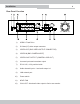
Installation 6 Rear Panel Function 1) USB2.0: Flash Drive 2) S-Video(Y/C) video output connector 3) VIDEO-OUT( BNC VIDEO OUTPUT CONNECTOR) 4) VIDEO-IN (BNC CAMERA INPUT) 5) VIDEO-LOOP OUTPUT (CAMERA LOOP OUT) 6) 4 sensor inputs and one alarm output 7) DC-IN 12V, 4.
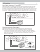
DVR Installation 7 Video Output connection to TV or monitor Please connect the TV or monitor input source to the video-out located on the back of the DVR. This unit provide an S-Video and 2BNC output connectors. Video output are used primary for monitoring and toggle between full screen and quad screen display. The call out connector is used for a 2nd or a son-monitor output to display full screen single channel with auto sequencing mode, no quad view.
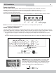
DVR Installation 8 Sensor Installation This unit contains 4 sensor inputs in which each sensor corresponds to the 4 channels. The sensor installation procedures are as follow. There are two simple step in installing the sensors. connecting the sensor signal line: connect the sensor signal line to DVR. The sensor signal terminal is located on the rear panel of the DVR. Then Connect the sensor jack to the sensor, and plug in the adaptor to an electrical outlet to power up sensor.
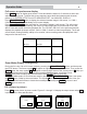
Operation Guide 9 Full screen or quad screen display Press QUAD button to display quad screen. Press and hold the button for 3 seconds to enter auto sequence display mode. To adjust the screen sequence auto dwell time between each channel, please go to SYSTEM SETUP into AUTO SEQUENCE SET into MON SEL: DISPLAY Press FULL/SEPARATE button to display the selected camera image in full screen, i.e. CAM 1, CAM 2, CAM 3 or CAM 4 individually in full screen display.
Operation Guide 10 Information Press INFO to get the following on screen display information; system setting, HD, firmware, etc. 0000 MASTER SLAVE HDD MODEL: Maxtor NO DETECT HDD Capital: 40G HDD USED: 0.07% HDD READ: 0.07% PB REPEAT: OFF OVERWRITE: ON REC SPEED: 50 Fld/1sec REC Letter: HIGH V. FORMAT: PAL IP ADDR: 010 192 001 124 S/W Ver: CR04U Vxx.xx USB Back-Up ( To back up data into USB Flash drive) Note1 : Video backup can only be done during Playback mode.
Operation Guide 11 Freeze Mode During the live camera view, press the stop button to freeze the image. The symbol F will appear on the top right hand corner of the screen. The freeze command can be use in both single channel view or quad channel view. Watermark Mode Watermark protection feature: It is to prevent any modification of the recorded data file . If there is modification; the watermark will not look the same.
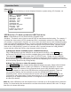
Operation Guide REC START/STOP SEARCH(Search by Start/Stop Time recording): RECORD SEARCH MASTER START TIME 04/06/2006 14:43 05/06/2006 03:10 05/06/2006 10:05 PAGE:0001/9999 END TIME 04/26/2006 14:46 05/06/2006 03:45 05/06/2006 10:23 ------------------------------------------------------------ENTER SET ↑↓← → EXIT START TIME: MM / DD / YYYY HH: MM (start of recorded file) END TIME: MM / DD / YYYY HH: MM (End of recorded file) The DVR can store up to 10 files to a page and 100 pages maximum.
On Screen Display Functions 13 Select TIME/DATE SEARCH to search for specific time/date by inputting the MM/YYYY HH: MM into the search, the search engine will start to search for the specified time and date. START: MM / DD / YYYY HH: MM (start/earliest date/time that exists in the hard drive) : END: MM / DD / YYYY HH: MM (End/last date/time that exist in the hard drive) M M / D D / Y Y Y Y H H : M M (this date/time area is adjustable for search).
On Screen Display Functions 14 TIME/DATE SET In the SYSTEM SETUP menu, select TIME/DATE SET and press [ENTER]. Press the UP/DOWN buttons to change the value. Press the FORWARD /REVERSE to select number category. Press MENU/ESC to return to SYSTEM setup.
On Screen Display Functions 15 FACTORY RESET In the SYSTEM SETUP menu, select FACTORY RESET and press ENTER. A warning screen will appear as shown below. Select YES or NO by pressing the FORWARD/REVERSE buttons then press ENTER to confirm selection. Press the MENU/ESC to return to the SYSTEM SETUP menu page.
On Screen Display Functions 16 SYSTEM SETUP ◎ TIME/DATE SET [ ] ] ◎ HDD FORMAT SET [ ◎ AUTO SEQUENCE SET [ ] ◎ FACTORY RESET [ ] ◎ PLAY REPEAT: NO ◎ VIDEO SOURCE: PAL ◎ BUZZER SOUND: ON ◎ PASSWORD ENA: OFF ◎ NEW PASSWORD: 0000 ------------------------------------------------------------ENTER SET ↑↓← → EXIT If the video standard setting is not set up correctly, resetting the DVR is required to default back to NTSC standard.
On Screen Display Functions 17 NEW PASSWORD In the SYSTEM SETUP menu, select NEW PASSWORD. Use the directional buttons FORWARD/ REVERSE to change value of the password. Use the Up/Down buttons to toggle between the first and the fourth digit setting. After changing from the manufacture default password, please remember the newly created password or jot them down and place it in a secure area.
On Screen Display Functions 18 BRI/CON SETUP In the VIDEO SETUP menu, select BRI/CON SETUP and press ENTER. Press UP/DOWN to select one of the four camera BRI/CON and press FORWARD/REVERSE buttons to adjust the value. Press MENU to return to the VIDEO SETUP menu page. The default value is the middle for both the BRI/CON.
On Screen Display Functions 19 VIDEO SETUP ◎ NAME SETUP [ ] ◎ BRI / CON SET [ ] ◎ BOUNDARY: WHITE ◎ BACKGROUND: BLUE ◎ LANGUAGE: ENGLISH ------------------------------------------------------------ENTER SET ↑↓← → EXIT RECORD SET Press the MENU button to enter the SETUP MODE. Browse to select RECORD SET and press ENTER to enter record setup as illustrated below.
On Screen Display Functions 20 The DVR support static IP address only, it will NOTsupport dynamic IP address. With a valid static IP address, please input them into each of the categories: SUB NET, GATEWAY, IP ADDR. If you are unsure, please contact your ISP (Internet Service Provider) for detail as to what type of IP you signed up for when registered. The NET CMD PORT and NET AV PORT are ports used to identity the DVR hardware.
On Screen Display Functions 21 COMPARE FRAME: 1~15(compare the changes of fields’ image for alarm trigger. 1=most sensitive 15=least sensitive) EVENT REC TIME: OFF, 1~99 MINS, CONTINUES ALARM OUTPUT: NO USE, 1~99 SEC, Always on (used for both sensor output and buzzer sound output) NOTE: To complete buzzer sound output settings; BUZZER SOUND located in the system Setup needs to be turn ON to activate alarm buzzer sound.
On Screen Display Functions USB FW UPDATE SETUP MODE ◎ SYSTEM SET [ ◎ VIDEO SET [ ] USB total size: 512 MByte Useful size: 512 MByte USB Firmware Update ] ◎ RECORD SET [ ] ◎ NETWORK SET [ ] ◎ SENSOR SET [ ◎ FW UPDATE [ 22 ] CONTINUE USB FIRMWARE UPDATE ? ] ◎ SCHEDULE SET [ ] Note: Only update firmware upon manufacturer’s request. SCHEDULE SET Press MENU button to enter the SETUP MODE, select SCHEDULE SET and press ENTER.
Network Viewer software To Install Network Netviewer Software: 23 Insert Netviewer CD into the CD-ROM tray, an install shield wizard will appear as shown below. If the install wizard fail to appear, please bowse the CD contents and double click on “setup.exe” file to exceute and run setup. Select a desire language, and then click “Next” to proceed. Press “Next” to continue the installation. To install a different folder, click Browse and select another folder. Then click “Next” to continue installation.
Network Viewer software 24 Setup will add program icons to the program folder listed below. Click “Next” to continue installation. Click “Next” to install NetViewer software.
Network Viewer software 25 Setup complete, Click “Finish”.
Network Viewer software To Uninstall Netviewer: 26 Go to start >programs/all programs> network viewer >uninstall Network Viewer or go to the system control panel>Add or Remove programs to remove Network Viewer. The following windows will appear: Click “Yes ” to proceed. Click “OK ” to complete uninstallation.
Network Viewer software 27 How to Use Network Viewer client software: To execute the Netviewer software go to start >all programs >Network Viewer > NetViewer4ch or double click on Netviewer4CH shortcut icon located on the desktop and a Network Viewer window will appear as shown below: Click the Setting icon on the Netviewer main screen, and the setting display box will appear. Input an IP address assigned to the local DVR.
Network Viewer software 28 Click the Connect button, and the Logon dialog box will appear. The DVR IP address will appear in the System field or click down arrow for options. Next input the DVR Password and click “OK” to connect. When successfully connected click OK. The live video display should start to stream. In any case if the video is not streaming simply click on the “PLAY FROM NETWORK” icon located in the upper right hand corner to start live view streaming as illustrated below.
Network Viewer software 29 LIVE VIEW Click on the Rec Start button to start recording on the local DVR from Network Viewer software and the red LED light will light up (lower-Right hand corner). Click on the Rec Stop button to stop the DVR recording and the red DVR LED light will gray out. Note: If the local DVR is initially in record mode, then using the Netviewer to remotely connect to the DVR, the Rec Stop button will not be active or unusable unless the Rec Start.
Network Viewer software 30 In the save to AVI window, select a save to location and give it a file name. Next select any combination of channels ranging from 1-4 to save and click OK to proceed. A blue LED located in the Lower-Right hand corner will appear. To stop AVI recording simply press on the “Save As AVI…” again. Please note, AVI playbacks require window media and the playback speed will be 3 to 4 times faster than the actual speed of the original recording.
Network Viewer software 31 SCANDISK Scandisk tab is used when the hard drive is removed from the inside of the DVR and connecting it directly to the IDE bus of the computer or via 3rd party External enclosure. This procedure is affective if there is something wrong with the DVR's ability to playback important recorded data. Please note that this is not one of the remote features used to control the DVR remotely. FILEPLAY FilePlay tab is used to retrieve saved .
Recording Time 32 Important Message: The higher the video quality, the clearer the picture. On the contrary, the lower the video quality setting can provide longer the record time. The record time varies depending on the field size and picture quality. The following record time tables can be used as a reference. The record time capacity can vary depending on the image complexity, color, black & white, brightness, contrast, image movement and background video noise.
Recording Time Recording Time Table: Based on 200GB HDD at PAL Field/Sec 100 50 25 Resolution Very High 33.7 67.3 High 46.3 92.6 720*240 Low 58.5 117.0 Very Low 61.7 123.5 Very High 34.7 High 46.3 360*240 Low 55.6 Very Low 61.7 33 Unit : Hours 12 10 140.3 192.9 243.7 257.2 168.4 231.5 292.4 308.6 5 3 2 336.7 561.2 841.8 1683.5 463.0 771.6 1157.4 2314.8 584.8 974.7 1462.0 2924.0 617.3 1028.8 1543.2 3086.
Recording Time 34 Recording Time Table Unit : Hours Based on 320GB HDD at NTSC Field/Sec Resolution Very High High 720*240 Low Very Low Very High High 360*240 Low Very Low 120 60 30 20 52.9 74.1 92.6 98.8 105.8 148.1 185.2 197.5 158.7 222.2 277.8 296.3 12 5 3 264.6 634.9 1058.2 370.4 888.9 1481.5 463.0 1111.1 1851.9 493.8 1185.2 1975.3 2 1 1/2 1587.3 2222.2 2777.8 2963.0 3174.6 4444.4 5555.6 5925.9 6349.2 8888.9 11111.1 11851.9 52.9 67.3 82.3 92.
www.securitymaninc.