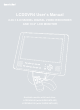
LCDDVR4 User’s Manual 2-IN-1 4-CHANNEL DIGITAL VIDEO RECORDER AND 10.
Copyright Notice This manual is furnished under license and may be used or copied only in accordance with the terms of such license. Except as permitted by such license , no part of this publication may be reproduced , stored in a retrieval system , or transmitted , in any form or any means , electronic , mechanical . Recording, or otherwise, including translation to another language or format, without the prior written permission of SecurityMan.
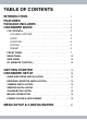
TABLE OF CONTENTS INTRODUCTION FEATURES PACKAGE INCLUDES HARDWARE BASIC LCD CONTROL 1 1 2 2 2 LCD MENU OPTIONS 3 AUDIO 3 FUNCTION 4 SYSTEM 5 PRESET 6 FRONT PANEL 7 REAR PANEL 10 SIDE PANEL 12 RC (REMOTE CONTROL) 12 GETTING STARTED HARDWARE SETUP 14 15 HARD DISK DRIVE INSTALLATION 15 EXTERNAL MONITOR INSTALLATION 15 CAMERA INSTALLATION 16 SENSOR INSTALLATION 17 ALARM INSTALLATION 18 MOUSE CONNECTION 19 POWER ON DVR & HDD FORMAT 19 MENU SETUP & CONFIGURATION 21
USING FRONT PANEL AND REMOTE CONTROL 24 USING MOUSE CONTROL 24 CAMERA 24 CHANNEL 25 DISPLAY 25 BRIGHTNESS 25 CONTRAST 25 HUE 25 SATURATION 25 RECORD 26 RECORD FRAMERATE 26 RECORD QUALITY 27 RECORD SCHEDULE 28 ALARM 30 ALARM DURATION 30 BUZZER DURATION 31 EVENT REC DURATION 31 SENSOR 31 MOTION DETECTION 32 SCREEN 34 BORDER 34 AUTO SEQUENCE 34 VIDEO ADJUSTMENT 35 AUDIO 35 SYSTEM 36 HARD DISK SETUP 37 OVERWRITE ENABLE 37 FORMAT HDD 37 ACCOUNT SETUP 39 A
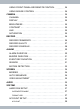
PASSWORD 40 LEVEL 40 PASSWORD/PASSWORD SETUP 41 KEYPAD TONE 42 TIME SET 42 EVENT LIST 43 PTZ SETUP 43 BUTTON FUNCTION FRONT PANEL/REMOTE CONTROL 45 REMOTE CONTROL 45 MOUSE FUNCTION 45 PRESET SETUP 45 PTZ MODE 46 ICON FUNCTION WINDOW 46 ATTENTION 46 F/W UPGRADE 46 LOAD SETUP DEFAULT 47 SEARCH:PLAYBACK 47 PLAYBACK CONTROLS USING FRONT PANEL OR REMOTE CONTROL (RC) 48 PLAYBACK CONTROLS USING MOUSE 49 BACKUP TO USB MEMORY STICK 50 LANGUAGE 52 LOGOUT 52 EXIT 53 SOFTWA
SOFTWARE BASIC & PLAYBACK 58 CONTEXTUAL MENU 61 OPEN FILE...F2 61 OPEN DISK 61 EXPORT (*.VVF TO *.
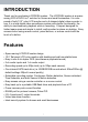
INTRODUCTION Thank you for purchasing LCDDVR4 system. The LCDDVR4 system is a spacesaving LCD & DVR 2-in-1 solution for homes and small businesses. It is composed of both 10.2” color LCD monitor and a 4-channel digital video recorder in one. It is a total digital video surveillance system with duplex functionality; the ability to simultaneously playback while in recording. Compact designed for limited space area and simple to install, wall-mounted or place on desktop.
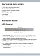
PACKAGE INCLUDES • LCDDVR4 w/ mounting bracket stand • Power adapter with cable • Remote Controller (batteries included) • PS/2 Mouse • Software CD (for PC) • User Manual • Ground Cable and screws Hardware Basic LCD Control Top Panel 1) MENU/POWER: Press and hold for 2 seconds to turn ON/OFF the LCD monitor. Press MENU/Power button to get to the LCD menu and press it again to browse through the display menu options. 2) UP: In the LCD menu, press the UP button to browse up the menu options.
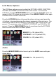
LCD Menu Options The LCD Menu options are use to adjust the PICTURE, AUDIO, FUNCTION, SYSTEM, and PRESET parameters of the LCD monitor. To access the LCD Menu press the MENU/POWER button once and the PICTURE menu will appear on the LCD screen as shown below. Press MENU/POWER button again to browse from one menu to the next. Press the UP/DOWN buttons to browse the picture sub-menu and press the +/- buttons to increase/decrease the value or parameter of the sub-menu.
Note: This is volume control for the LCD monitor and it is the master volume control that dominates over the recorder’s volume control. If volume level is set too high, the microphone gain from the camera may sound distorted. The AUDIO menu is use to adjust the LCD volume level which dominates over the recorder’s volume control level. Press the +/- buttons to increase/decrease the volume level of the LCD monitor. The manufacture default volume level is set at 27 percent.
change to display in 4:3 ratio. To toggle between the display ratio press the + or – buttons. Press the MENU/POWER button 3 more times from the FUNCTION menu to exit out from the LCD Menu options. System Press the MENU/POWER button 4 times to get to the SYSTEM menu setting as shown below. S-ROLOC: AUTO, NTSC, SECAM, & PAL (default AUTO) Note: Please use default AUTO setting unless the video format intended does not display correctly.
Preset Press the MENU/POWER button 5 times to get to the PRESET menu setting as shown below. SLEEP: 0~24 0Mins. (default 0) TIME: setup current time (default --) OFF-TIME: setup time for LCD to turn off (default --) ON-TIME: setup time for LCD to turn on (default --) Note: OFF-TIME has to exceed the TIME and ON-TIME. SLEEP (countdown timer) and TIME (interval) feature works and operates independently. The PRESET menu is use to setup SLEEP and TIME (OFF-TIME, ON-TIME).
Front Panel The front panel consists of a LCD display screen (above the function buttons), a speaker (to the left of the function buttons), and DVR function buttons use to control and configure the DVR. The front panel buttons is use to operate the DVR’s basic functions such as; record, playback, fast-forward, reverse playback, and etc.
again to start playing back the oldest data that exist in the hard drive. From the Time Search menu option, press the SEL/EDIT button to enter query time/ date search. Press the UP/DOWN button to browse and press the SEL/EDIT button to change the value. Press the MENU/ESC button to accept and confirm time/date search and then press the PLAY button to start searching. In play or playback mode, press the MENU/ESC button at any time to activate file backup, please reference file backup section of the manual.
frame-by-frame. To continue normal playback, press the PLAY button. 8) MENU/ESC button is use to access the main menu of the DVR. The main menu is use to configure and setup parameter of the DVR. Press the ▲ UP/ ▼ DOWN button to browse through the main menu. In playback mode, the MENU/ESC button is use to access file backup panel. Press the MENU/ESC button at anytime to exit out from the menu. 9) ▲ UP / ▼ DOWN button is use to browse/toggle or change a menu field.
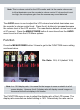
Rear Panel The rear panel of the LCDDVR4 consists of ports and interfaces for video inputs, video output, audio inputs, audio output, power socket, mouse port, HDD bracket, I/O terminals and bracket stand. The picture below shows a list of basic ports, I/O interfaces and connections: 1) DC 12V: An AC/DC power socket for power adapter input. Connect using the power adapter provided; plug the power jack to the DC 12V socket and then plug the power adapter to an electrical outlet.
5) AUDIO 1/2 IN: Connect up to 4 audio microphone cameras into the audio input ports. Only one audio port can be active for monitoring and recording. If one audio input is connected into AUDIO 1 IN and the AUDIO menu is setup for channel 1, audio will output in channel 1 full screen view and in quad view. However, if audio input is connected to AUDIO 1 IN and AUDIO menu is setup for channel 1, viewing channel 2/3/4 in full screen will mute the audio output.
Side Panel The right side panel consists of a USB port use for backup purposes and update firmware. The USB port is dedicated for backup purposes only; alternatively, USB mice will be compatible and will not function through this USB port.
1. CH1 ↑ 5. QUAD 6. ◄◄ / Z7. ► / F+ 8. ►► / Z+ 9. ● 10. ▌▌ / F11.
GETTING STARTED Install a SATA hard disk drive into HDD bracket located at the back of LCDDVR4 panel by removing the four screws (Philips) from the HDD bracket. Connect the data and power cable to the SATA hard disk drive, seat the HDD bracket back into the slot and secure it with the four screws. Hook up to 4 cameras with BNC interface into the video inputs of the DVR. Connect the PS/2 mouse, external sensors (if any), alarm, GND cable, audio in/out, and etc. into the DVR back terminals.
HARDWARE SETUP Hard Drive Installation To install a SATA hard drive into the LCDDVR, please remove the four screws from the HDD bracket located in the back panel of the DVR (Step 1). Setup the jumper setting on the SATA hard drive to either 1.5Gb/s or 3Gb/s operation, prefer to set to 3Gb/s (Step 2). Secure the hard drive to the HDD bracket with the provided HDD screws (4x). Then connect the Power and Data cable of the DVR to the SATA hard drive (Step 3).
The DVR VIDEO OUT to External monitor VIDEO INPUT. DVR OUT to external monitor Monitor “VIDEO INPUT “ from DVR Camera Installation Connect the camera’s Video Output to the Video Input “IN1~4” of the DVR located in the rear. Plug the camera power to the camera and the other end into an electrical outlet. Connection diagram illustrated below. Note: Camera using RCA interface connection requires an additional RCA female to BNC male adapter.
Sensor Installation There are a total of 4 sensor input terminals located in the rear of the DVR. The sensor input is use to setup hard wire external sensor such as motion sensor, window/door sensor, and etc. Since the terminal does not provide power to the input devices, the sensor is required to have its own power. There are two simple steps to install hard wired sensor input as follow: • Choose one of the four terminals to connect the sensor into.
Normally Close Normally Open (Common) Normally Close & Open (N/A) After the sensor hardware has been setup according to the above illustrations, next is to activate the sensor via the MENU setup on the LCDDVR4. To active the sensor in the MENU setup please advance to page 28 and 29 of this manual. Alarm Installation The unit provides 1 internal switch for sounding alarm when the sensor is activated. The switch is open at normal state a wiring diagram is illustrated below.
Mouse Connection Connect the PS/2 mouse to the PS2 MOUSE port of the DVR located in the back of the DVR. Mouse control is one of the most convenient way of controlling the DVR, setup and configure the DVR. If mouse is lost or stolen, any PS2 mouse should be fully compatible with PS2 MOUSE port and DVR. Power On DVR & HDD Format Connect the power jack (Input: AC 100~240V, Output: 12VDC 5.
After the initial boot, the DVR advance to the user interface screen.
MENU SETUP & CONFIGURATION To enter the MAIN SETUP MENU press the Menu/ESC button on the remote control, front button panel or right-click button on the mouse and a login window will appear as shown above. There are three Account/Password level; the Admin account (highest, default), the Operator account, and the Guest account (lowest). By default the system has the password set to ON which require operator to input in a login name or account and a login password.
view channel 1~4], [playback recorded image file], [setup>camera> channel 1~4], [setup>alarm>motion detection>channel view 1~4], [setup>screen> boarder/auto sequence], [setup>audio>channel 1~4], [setup>system>password setup/password on-off/key tone/event list], [setup>search for playback recorded image files or events], and [setup>language selection]. In Guest account login, the identifier “ ” icon will appear on the top right hand corner of the screen if the restricted setting(s) is selected.
Setup Icon menu window (mouse only): Channel 1 full screen button Channel 2 full screen button Channel 3 full screen button Channel 4 full screen button Quad Channel view button Manual Start/Stop REC button Playback Time Search button PTZ switch Channel auto sequence button *The auto sequence icon “ ” will not show in the Setup Icon menu window if the “Auto Sequence” feature is turn OFF.
Using Front Panel and Remote Control Press the Menu/ESC button on the front panel or remote control to access the Setup menu list. Press the UP and DOWN button on the front panel or remote control to browse up and down the Setup menu. Press SEL/EDIT button on the front panel or remote control select and enter the sub-menu.
Camera menu consist of Channel, Display, Brightness, Contrast, Hue, and Saturation. CHANNEL Channel is use to toggle between camera channels, ie channel 1, channel 2, and etc for the purpose of adjusting and fine tuning the camera image. Channel name 1, 2, 3, 4 cannot be change. Or, press the left and right arrow of the front panel or remote control to change value respectively. DISPLAY Display can be use to turn ON (Default setting) or turn OFF the channel name display.
Note: The manufacturer default setting for Brightness, Contrast, Hue and Saturation is centered at 50%. RECORD Select Record from the Setup menu to get to the record setup menu as show below. The Record setup menu consists of Record FrameRate, Record Quality and Record Schedule. Press the Menu/ESC on the front panel, remote control or single right-click on the mouse at any time to exit out of Record menu to the main Setup menu.
OFF, 3fps through 30fps. To change the value, press the CH3←/CH4→ buttons on the front panel, remote control or left mouse click on the ◄ ► red arrows to decrease and increase [Select/Enter button on the front panel or remote control (RC) can also be use to increase frame rate value] the recording frame rate respectively. The higher the record frame rate the more natural the movements will be in playback mode.
RECORD SCHEDULE In the Record setup menu browse down to select Record Schedule, press the Menu/ESC button on the front panel, RC (Remote Control) or left mouse click to access the Record Schedule window as illustrated below. Press the CH1↑/(UP), CH2↓/(DOWN), CH3←, CH4→ buttons on the front panel, RC or mouse to move around to the time and days of the week and then press the Select/Enter button on the front panel, RC or left mouse click to change value box.
left mouse click twice to change from gray bar to red bar and into the bar for motion record schedule. green Sensor record; move the cursor to highlight the desire time/date of the week and then press the Select/Enter button on the front panel, RC (Remote Control) or left mouse click three times to change from gray bar to yellow bar and into the yellow bar for sensor record schedule.
not move the mouse or mouse tracking after the left button is released) and then left click once on the mouse to mask the bars to Time Schedule (red bar), left click again to mask Motion Schedule (green bar), and so on. ALARM To access Alarm setup menu, simply browse and select Alarm from the Setup menu and then the Alarm setup menu will appear as shown below. Alarm menu is use to setup and configure Alarm Duration, Buzzer Duration, Event REC Duration, Sensor (I/O) and Motion Detection (built-in MD).
BUZZER DURATION Buzzer Duration refers to the built-in buzzer sound when the alarm triggered. It can be set to OFF (system default), 5 seconds, 10 seconds, 15 seconds, 20 seconds, 25 seconds, 30 seconds, or CON’T (Continuous). As its name imply, Buzzer Duration is use to configure the length of time the buzzer will sound when an event occur. Buzzer Duration is works independently from Event REC Duration time setting.
From the Alarm setup menu select Sensor to get to the sensor menu as shown above. Sensor setup defined the native state of the wired sensor that is installed in the I/O terminals. There are three different types of sensor setting: N.O (Normally Open), N.C (Normally Close), & NONE (system default). The wired sensor statue may vary depending on manufacturer make; most common setting is N.O (Normally Open) state. If unsure please refers to the user’s manual of the input device.
Sensitivity is use to adjust the sensitivity level of video motion detection (built-in software driven) on the DVR system. The sensitivity value level can be set to 1, 2, 3, 4, and OFF (system default). The most motion sensitivity level is 1; the higher the number, the less sensitive the video motion detection which requires more movements in the image to trigger motion sensor.
SCREEN In the main Setup menu browse down to Screen and press Select/Enter using the front panel, RC or left mouse click to access the Screen setup menu as illustrated below. The Screen setup menu can be use to configure Border, Auto Sequence, and Video Adjustment. BORDER On the Screen setup menu, select Border. The Border configuration when turn ON (system default) will divide the quadrant with a gray cross between the four channels. This helps to distinguish the border line for each channel.
To deactivate Auto Sequence mode; press the Menu/ESC button on the front panel or RC, select Screen from the menu and disable Auto Sequence by setting it to OFF. For temporary disable without turning the Auto Sequence off, press the ►► button once to intermit auto sequence. To deactivate Auto Sequence using mouse function; right mouse click anywhere on the image to get to the Icon Setup Menu and then click on the icon.
From the main Setup menu browse down to Audio and press Select/Enter using the front panel, RC or left mouse click to access the Audio setup menu as illustrated above. The Audio menu consists of Channel, Record, Mute and Volume. Select the channel/camera to setup audio configuration. Then set the Record to ON (require microphone device to be attached to the Audio Input of the system, system default) for audio recording or OFF to disable audio recording.
HARD DISK SETUP Select Hard Disk Setup from the System menu to get to the hard disk setup windows as shown below. OVERWRITE ENABLE In Hard Disk Setup menu set Overwrite Enable to Yes (system default) to allow the system to continue to record and overwritten the oldest data by the minute when the hard disk filled up. Set the Overwrite Enable to No will stop the DVR from recording when the hard disk filled up.
To proceed with hard disk format; select or click on Format HDD and the Format HDD window will appear as shown below. To continue with hard disk formatting; input an Admin login password and then select or click on “Enter” to start the formatting process. A Format HDD … window will appear during the formatting process and then follow by a HDD was formatted window to complete the formatting process as illustrated below.
ACCOUNT SETUP From the main System menu browse down to Account and press Select/Enter using the front panel, RC or left mouse click to access the Account setup menu as illustrated below. Account menu login is restricted for Operator and Guest account users, only the system Admin login can edit the Account menu. The Account setup menu allows the system administrator to add new user accounts, delete existing accounts, and modify the user’s name, password and account level.
Password To setup a Password for the user account, please repeat user account setup procedures above only select the Password cubical and a window will appear as shown below. The account Password can be up to 6 digits long and can be of any combinations of numbers, letters, and symbols. Click Enter when finish.
PASSWORD/PASSWORD SETUP System administrator login; from the main System menu hover down over to Password and then press Select/Enter using the front panel, RC or left mouse click to toggle the password setting ON (system default) or OFF. Notice that Password Setup does not exist in the System menu under system administrator login.
KEYPAD TONE From the main System menu browse down to Keypad Tone and then press Select/Enter using the front panel, RC or left mouse click on the red arrow buttons to toggle between ON or OFF (system default). If the Keypad Tone is set to ON will enable keypad tone during system operation. Turn the Keypad Tone to OFF will mute the keypad tone during system operation.
EVENT LIST From the main System menu browse down to Event List and then press Select/ Enter using the front panel, RC or left mouse click to access the Event List window as shown above. The Event List shows the list of events that occurs in ascending order from recent file to past history files, the event Start date/time and event End date/time, color coded bars to designate event types, and the event Page number. The first Event List start with 001 and the maximum event list is 300.
Enter using the front panel, RC or left mouse click to access the PTZ Setup window as shown below. LCDDVR4 supports 2 type of protocol cameras; Pelco-D and Pelco-P protocols. Adjust the RS485 setting according to the PTZ protocol camera and then match the Address, Protocol, and Baudrate setup to the camera settings. To setup PTZ protocol camera, change the Channel to the PTZ camera. Set the dome address number or dome’s identification number ranges from 0~255.
al speed and set to 1 to slow the rotational speed, the system default setting is 8. PRESET: Ranges from 1~32 for PELCO-D protocol camera and 1~255 for PELCO-P protocol camera, the system default setting is 1 for both protocols. When 0 is display, the preset is not use. Press the Menu/ESC button on the front panel, RC or right mouse click on the mouse at anytime to exit out from the PTZ setup window. Button function Front Panel / Remote Control [SEL/EDIT]: To select or increase value.
Then press [Select] button to finish the order of Auto scan, the dome will run on presets positions unless the [STOP]button is pressed on to stop Auto scan. PTZ Mode Select PTZ mode and then right mouse click in PTZ mode to bring up the Icon function window as shown below. Icon function window ▲▼►◄: are directional movements for the dome: upward, downward, leftward and rightward. ■: Stop the dome from moving in auto scan mode. : Focus image. : Zoom in/out of view. : Auto scan, require preset setup.
upgrade searching window. The F/W upgrade is use to upgrade the firmware of LCDDVR4 system to its availability. To update the firmware, make sure the firmware file is copied into a root directory of a USB thumb drive or USB flash drive, insert the USB (thumb/flash) drive into the USB port on the right side of the DVR and then select F/W upgrade to proceed with firmware update.
CH1↑(UP)/CH2↓(DOWN) buttons on the front panel, RC or hover the mouse over the search query box, press the SEL/EDIT button or left mouse click to enter query, press the CH3←/CH4→(SEL/EDIT) buttons to decrease/increase or mouse click on the red arrows to decrease/increase time/date value, and then press the Menu/ESC button (front panel, RC) or right mouse click to confirm. Finally, press the Search to playback.
times the normal speed and the ◄◄◄ green icon will display on screen to indicate 3X REW. REW3 - Press the ◄◄ REW button three times to rewind (REW) playback at 4 times the normal speed and the ◄◄◄◄ green icon will display on screen to indicate 4X REW. To toggle between the fast forward and rewind speeds, press the FWD or REW buttons once, twice, or 3 times during playback to fast forward or rewind the video footage.
BACKUP to USB Memory Stick To backup to memory stick or thumb drive, in playback mode: 1. Use search query (Search:Playback above) to playback the file for backup. 2. Plug in a memory stick or thumb drive (fat 32 file formatted) into the USB port located on the right side of the LCDDVR4. 3.
on Start to start video backup to external USB memory stick. Press or click on Cancel to cancel the USB backup process. The backup process can take anywhere from a few seconds to a few minutes long depending on the backup size selected for backup. 7.When the backup is completed, press or click on Exit to exit out of Backup to For example: to backup a 1 minute file or about 27MB size will take approximately 1 minute and 50 seconds on average. USB window and back to live display screen as shown below. 8.
LANGUAGE LCDDVR4 supports multi-lingual on screen display. From the main Setup menu browse down to Language and then press Select/Enter using the front panel, RC or left mouse click to access the Language window as shown on the right. Choose desire language; English, Italiano, Polski, Espanol, Francais, Greco, Deutsch, Nederlands, Portugues, and Turkce. Press the Menu/ESC button on the front panel, RC or right mouse click on the mouse at anytime to exit out from the Language window.
EXIT Exit is use to exit out from the system setting. From the main Setup menu browse down to Exit and then press Select/Enter using the front panel, RC or left mouse click to exit out from the Setup window and a confirmation exit window will appear as shown below. To Exit and save the changes, select the Exit & Save Changes, to exit without saving the changes, select the Exit & Discard Changes.
SOFTWARE INSTALLATION To install the PC player for windows, please follow the necessary steps below. PC player software is use to playback the backup video files from the LCDDVR4 and it is included inside the CD provided. Note: Software compatible with windows 2000, XP, Vista, & 7, not compatible with windows running on 64-bit operation system. Step 1: Put the software included in the CD into the CD-ROM drive.
Click Next> Click Next> 55
Check “Create a desktop icon” and then click Next>. Step 4: Click on Install to start the installation process as illustrated below.
Step 5: Installation is complete, click on Finish as shown below. SOFTWARE UNINSTALLATION To uninstall PC player software, go into c:\Program Files\VxViewer folder and then double click on unins000.exe and click on Yes and follow through to uninstall VxViewer, as illustrated below.
PC PLAYBACK Software Basic and Playback Double click the icon located on the desktop to execute PC playback software and the GUI (Graphic User Interface) window will appear as shown below.
1. Open File 2. Fast Backward (Rewind) 3. Play Reverse 4. Previous Frame 5. Pause 6. Next Frame 7. Play 8. Fast Forward 9. Still Capture 10. Split 1 (Single Full Screen) 12. Volume (Scrollable) 11. Split 4 (QUAD) 13. Mute On/Off 14. Play Bar (Scrollable) 15. Minimize Window 16. Close Program The LCDDVR4 backup files are in *.VVF file format which is a proprietary format (not standard format) and can only be playback using the software provided. To playback *.
During video playback use the Playback Control Buttons located at the bottom Fast Backward or Fast left of the player as shown below. Press on Forward button once to rewind or fast forward at 2x the normal speed, press twice for 4x, press three times for 8x, press four times for 16x, press five times for 32x, and press six times for 64x.
mouse click anywhere on the software window, select Options, modify the Path for still capture by clicking on the Browse button, and then browse to a folder as illustrated above. Click on the Split 1 or the Split 4 button to view single camera in a single full screen or 4 split screen mode respectively. Single full and quad screen can be use in both live view or in playback mode.
Note: Open Disk playback is a physical disk playback which requires LCDDVR4 hard drive to be connected directly into a PC or otherwise, Open Disk option feature will not work and fail to detect HDD. Export (*.VVF to *.AVI Conversion) In the Contextual Menu, click on Export and then select AVI (Audio-Video Interleaved Files) and an Export To AVI window will appears as illustrated below. In the Export TO AVI window; select Export Channel (1~4), select or deselect Audio, click to browse for *.
Note: It is recommended to select Uncompressed in Video Compression. However, please be sure to test all the different compression type available and to ensure the selected compression works; compression availability varies depending on computer. Close or F4 The Close or F4 command will close out from or exit from the existing playback file and most of the playback controls in the lower left will be grayed out pending for Open File.
Always On Top Select Always On Top to put the Vx4SLPlayer window on top of all other windows on the desktop. If this option is not selected other windows application(s) can cover over the Vx4SLPlayer window. Playback Please reference playback on page 47 above for detail. Capture Capture is use to shorten the video clip into a shorter segment clip, VVF to VVF file. To Capture shorter clip; pause playback, drag Play Bar to desire start time and select Mark In under Capture in the Contextual Menu.
Audio Select Volume UP and Volume Down to adjust the volume level as accordingly. Select Mute On/Off to enable or disable the audio playback feature as shown below. When mute is Off, use the Volume scroll bar to adjust the volume to a desire level. Full Screen Select Full Screen to view playback in a full screen display. In Full Screen view, Contextual Menu becomes very useful as the Playback Control Buttons in the lower left cannot be use.
□ Show playback time (T): Check to display time/date during playback. Uncheck this option to disable the time/date display during playback. Select from the drop down menu of On screen display date/time format to display different date/time format. Click under Path for still capture to select a folder location to store snapshoot images, default C:\VxCapture. Click to accept and exit out from Options setup window.
APPENDIX RECORD TIME Recording Chart (Models: LCDDVR4-80/-320) Format Record Quality Speed 60 fps 30fps (default) NTSC 15fps 50fps PAL 25fps (default) 12fps Data Size Data Rate HDD(SATA) KB/Frame GB/Hour 80GB(Hours) 320GB(Hours) High 26 5.4 15 60 Normal 16 3.3 24 96 Low 13 2.7 30 120 High 26 2.8 28 112 Normal (default) 16 1.6 50 200 Low 13 1.3 62 248 High 26 1.3 62 248 Normal 16 0.8 100 400 Low 13 0.7 114 456 High 26 4.4 18 73 Normal 16 2.
SPECIFICATIONS ITEM DESCRIPTION NOTE Monitor 10.2” COLOR LCD, Desktop or Wall-mount 800X480, 300:1, 450NIT, VIEW ANGLE 120º Video Format NTSC / PAL Operation System Linux OSD Support Multilingual Camera Input Channel 4 channel Composite BNC Video Output Channel 1 channel Composite BNC Recording Frame Rate NTSC: Max 60fps (total), 30fpt (each ch) PAL: Max 50fps (total), 25fps (each ch) Record Mode Manual Rec., Time schedule, Motion detection, Sensor Rec.
Audio Input 2 Channel Composite RCA Audio Output 1 Channel Composite RCA USB YES Remote Control 38KHz IR PS/2 Mouse 3 Button Optical Mouse Power Input: 100~240VAC Output: DC12V 5A, positive inside. Dimensions (L x W x H) 290 x 230 x 70 mm (11.4” x 9” x 2.8”) Not including bracket Weights (Net/Gross) 6 lbs (LCDDVR only) / 8.
COMPATIBLE USB FLASHDRIVE Here is a list of flash drives that has been tested to comply with LCDDVR4: MAKER MODEL SIZE SONY MICROVAULT (SOK-USM1GJ) 1GB MEMOREX Travel drive 512MB MEMOREX Travel drive 2GB SAMSUNG SUM-LCB1 1GB TRANSCEND JF V30 2GB APACER Weblink (SYE5003358) 2GB SANDISK CRUZER micro 4GB FLEX FD-02 1GB KINGSTON Data Traveler 2GB KINGSTON Data Traveler 1GB LEMON LEMON USB Drive 1GB Q&A 1) I cannot backup to my USB thumb drive or flash drive? Sometimes power f
2) I cannot playback the VVF files on my computer? If PC playback fails do the following: A) Plug the USB drive into another available USB port on the computer. Ensure the USB is one of the built-in ports on the computer. Check if the flash drive or thumb drive mount on the computer. B) Re-install the player software from the CD. 3) I cannot load system default? Boot up the DVR and then press the QUAD button on the front of the DVR 20 times will reset LCDDVR4 to manufacturer's default setting.