2 3 9 6 CLOCKCAM-WIFI User’s Manual Wall Clock iSecurity Camera with Micro SD Recorder
© Copyright 2015 This manual is furnished under license and may be used or copied only in accordance with the terms of such license. Except as permitted by such license, no part of this publication may be reproduced, stored in a retrieval system, or transmitted, in any form or any means, electronic, mechanical, recording, or otherwise, including translation to another language or format, without the prior written permission of SecurityMan.
Table of Contents NOTE: PTZ & I/O features may not be applicable to your device.
Password Zone Domain Cloud Edit Device Add Device Example How to Add the IPcam-SD to the CMS Modify Delete Import Config Export Config Connection Test IPCam Config Device List Sub-Menu Icons Main Menu Icons REC/Playback Video Snapshot Alarm Video Motion Video Blind Alarm Input Alarm Output Abnormal System General System Time, Date Format, Date Separator, Time Format, Language, HDD Full, Video Standard, DST (Daylight saving Tim
Introduction Stay connected wherever you go with the SecurityMan IP camera. You can remotely access your IP camera from anywhere in the world; monitor your home or business through a secure and password protected connection from your PC, Mac, iPhone, iPad, iPod Touch, or any compatible Smartphone.
Restrictions When using this product, the safety precautions below must be taken to avoid possible legal liabilities and damages. Retain and follow all product safety and operating instructions. Observe all warnings in the product operating instructions. To reduce the risk of bodily injury, electric shock, fire and damage to the equipment, observe the following precautions. PLEASE NOTE that under certain circumstances, audio/video recording may be PROHIBITED by law.
Conditions Please read the following messages to make sure your working environment is suitable. • Please read the following messages to make sure your working environment is suitable. • The temperature should be kept between –10˚C and 50˚C (14˚F to 122˚F). The relative humidity should be kept between 20% and 80%. • Avoid putting the product in places where temperature or humidity may change rapidly. • Keep it dry, dustless and avoid lens exposure in direct sunlight.
Package Contents CLOCKCAM-WIFI (Main Unit) Network Dongle SecurityMan¨ SecurityMan¨ VIDEO/AUDIOVIDEO/AUDIO MONITORINGMONITORING AND AND RECORDING DEVICES RECORDING DEVICES IN USE ON THESE IN USE ON THESE PREMISES PREMISES www.securitymaninc.com www.securitymaninc.
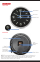
Product Basics Front View Minute Hand Hour Hand Second Hand Camera Lens Rear View Wall Mount Clock Adjustment Battery Video Out Reset Button Ethernet Port (Detachable) Micro SD Slot Power Socket NOTE: The reset button located on your camera is used to reset the IP camera to its original “factory default” settings. To apply, power up your camera then press and hold-in the reset button using a small non-pointed/non-metallic instrument (paper clip or other stationary) for 15 seconds.
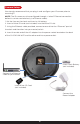
Camera Setup We strongly recommend that you plug in and configure your IP camera prior to mounting it. NOTE: The IP camera must be configured through a “wired” Ethernet connection before it can be used wirelessly (no Ethernet cable). 1. Set the time on the clock and insert a AA battery. 2. Insert a Micro SD card (not included) into the Micro SD slot. 3. Using the Ethernet cable provided, connect one end into the “Ethernet” port of the clock and the other into your router/switch. 4.
Phone Setup By User: 1: You can sync your IP camera to your user information by registering on xmeye. net. Once you select “Login”, your camera screen will be displayed immediately. 2: Begin by opening Internet Explorer and going to http://www.xmeye.net (fig. 1.1). Select “Register” and input your information into the available fields (fig. 1.2). NOTE: Username, E-mail, and Password are required fields. Fig. 1.1 Fig. 1.
3: Once you have filled out the information, press OK. A prompt showing “You have registered successfully!” will be displayed (fig. 1.3) Fig. 1.3 Fig. 1.4 4: Go back to the login page and login using your registered ID and PW. 5: Select “Device Manage” and select “Add” (fig.1.4) 6: The SerialNo. is the serial ID of the IP camera which you can obtain by scanning the QR Code located on the device (please refer to the QSG for instructions on how to scan the QR Code).
1: This method is used to add your IPCam without registering your user information. There are numerous ways to add/view your IP camera under “By Device”: QR Code, Search in LAN, and Address 2: Serial / QR Code: Please refer to the Quick Start Guide 3: Search in LAN: A) Make sure that your phone is connected to the same router as the IP camera B) Begin by pressing “Add” and selecting the “Search in LAN” button (fig. 2.1) C) Your IPCam device will display in a list form. Press on the + button (fig. 2.
Fig. 2.
D: Full screen mode: Double tap the camera screen to view it in full screen E: Panning: You can pan the camera using the Up, Down, Left, and Right arrow keys F: Zoom In/Zoom Out: You can zoom in and zoom out of the device. Not applicable for IP camera G: Close/Far: You can zoom up to a specific section of the camera. Not applicable for IP camera H: Aperture: Configure the opening of a lens’s diaphragm through which light passes.
1: Ethernet: Configure your Ethernet settings through your phone. Your IP camera must be connected to your router 2: Wi-Fi: Setup your wifi by searching for your router and inputting your password through the phone 3: Time Setting: Able to change the date format and format 4: System Setting: Displays IP camera firmware. Performs IP camera reset. 5: Video Setting: Changes the quality of the video, resolution, frames per second, bitrate, etc. 6: SD Card Info: Displays information on the SD card.
Remote Playback The remote playback searches for recorded files that were saved onto the SD card in the IP camera. You may select through the date, time, and type of recorded files (i.e. Motion recording, snapshots, video blind, etc.) Local Snapshot You can view the IP camera snapshots which were taken on the IPCam app. You can save the snapshots onto your phone’s photo gallery or delete them.
IPCam Live Setting Configures the settings for the IPCam application on your phone. Configurations include alert sounds, audio, video ratio, wifi network, etc. About & Help Information on the IPCam application and contact information are located on this page.
Software (CMS) Installation System Requirements • Operating System: Windows XP, Vista, 7 and 8 (32-bit/64-bit OS) • Processor: Intel Pentium 4 (2.0GHz or above) • Video Card: NVIDIA GeForce 6800 equivalent or better • Memory: 2GB RAM • Storage: 1GB available hard drive space • Internet: Broadband Internet connection 1. Insert the Installation CD into the CD-ROM drive, and double click the “Open folder to view files” option from the the AutoPlay window. 2. Next, double-click on the “CMS_V3.0.9.14.T.20130410.
4. Input the user name and company name. Then click “Next” to continue as illustrated above. 5. The default Install CMS directory is C:\Program Files\CMS, click “Change” to select a different destination folder, or click “Next” to continue (recommended). 6. The default shortcut icon folder is CMS. Click the drop-down menu for more selections, or click “Next” to start installing the CMS to your computer (recommended) as illustrated above. 7.
IP Address Setup 1. Double-click on the “CMS” short-cut icon on your desktop. Select “English” or other languages and then click “OK” to advanced to “Device list is empty, please add device...” prompt. Next, input the User Name and Password at the login window as illustrated below. The default User Name is “super” and the default Password is empty. Click the “Login” button to login to CMS. A “Device list is empty, add your...” window will appear as shown below, click on “OK” to continue.
5. In “Add/Remove IPCam” window, click to highlight “Demonstration” then click “ADD DEVICE” to open “Edit” device window as shown below. 6. On the “Edit”device window click on “IP Search”. Click/highlight the very first IP address that is displayed, click on “OK” to add the device and close out any open windows till you get tot he live view screen.In “EditDevice” window, please modify the default IP Address (Ethernet), Subnet Mask, and Gateway to match your local area network settings.
3. In “PC Config” window under “Base Config”, the default directory are C:\ Program Files\CMS\Record(Picture) folders, click “Browse” to choose a different destination folder. Next, select the “Record Setting” and make sure “Overwrite” is checked and then select the disk/partition you want save the video/picture files as illustrated below. Click “Apply” or “OK” to confirm the changes, and click to go back to main CMS screen. 4.
CMS Graphic User Interface A. Device Display Area F. Operation Log B. Display Screen G. Time C. Horizontal Expand H. Local Disk Status D. Multi-Screen View I. Right Click Menu E. Vertical Expand J. Menu Area A. Device Display Area The DEVICE DISPLAY AREA lists all the devices IP cameras that are accessible through the CMS software. Device display area can be added through the “Add/ Remove IPCam” under System in the menu area.
E. Vertical Expand Clicking on the VERTICAL EXPAND will hide the operation log area giving you a larger view of your cameras live feed. F. Operation log The OPERATION LOG area displays real time alarms based on the IP camera alarm notification settings. For example, if you set up “Video Blind” warnings for camera 1, the operation log window will display a message showing the event type, date/time, IP address, user and the channel number when an event occurs. G.
Menu Area The MENU AREA is located at the bottom right corner of the CMS interface and is designed to give you quick access to the most commonly used features such as PTZ Controls, Color Adjustment, Playback and CMS configuration and Playback. The menu area consists of the following: PTZ Color System Playback Logout NOTE: The area above the MENU area will change to correspond with options that are related to the menu option selected.
PTZ Selecting the PTZ option from the menu area of the CMS interface will bring up the PTZ control window which will allow you to maneuver and control your camera(s). To access the PTZ control menu simply click on the “PTZ” option from the CMS interface screen located on the bottom right hand corner of the screen. Once selected, the PTZ control screen will pop up providing you with the following options: A. Navigational Arrows D. Preset B. Speed Bar E. Tour C. Pan A.
D. Preset The PRESET bar allows you to create up to 255 preset camera points/positions. By creating a preset point you can have the IPcam-SD memorize the position of the camera and use a number (PRESET) to identify its position which can then be played back by using the TOUR feature.
Color The COLOR menu consists of settings that will allow you to control the picture quality of your IP camera. To access the color control menu simply click on the “Color” option from the CMS interface screen located on the bottom right hand corner of the screen. Once selected the, the color control screen will pop up providing you with the following options: A. Brightness D. Hue B. Contrast E. Default C. Saturation A.
System The SYSTEM menu consists of settings that will allow you to configure CMS features and options such as adding/removing cameras, creating users, viewing logs, etc. To access the SYSTEM control menu simply click on the “System” option from the CMS interface screen located on the bottom right hand corner of the screen. Once selected the, the system control screen will pop up providing you with the following options: A. PC Config – consists of basic CMS network and recording settings. B.
• PC CONFIG PC Config consists of four tabs that are used to configure how the CMS software will work in conjunction to your computer. These categories are: A. Base Config – CMS recording configuration. B. Alarm Setting – CMS alarm configuration. C. Record Settings – Allows you to program the IP camera to record on specific days and times. D. Version Info – Displays detailed device information.
• • BASE CONFIG The “Base Config” tab located in the PC Config settings consists of 6 categories that will let you configure how the CMS software will record and operate. These categories are: A. Log Maintenance – IP camera alarm log configuration. B. Snapshot – snapshot file path and format settings. C. Local Record – event (recording) file path configuration. D. Device – used to configure the cameras start up options. E. Sync Time With PC – schedule date/time sync configuration. F.
• • • LOG MAINTENANCE The LOG MAINTENANCE area located on the Basic Config tab consists of 3 settings that are used to configure the CMS log parameters. These settings are: SAVE ALARM LOG (DAY) The SAVE ALARM LOG (DAY) feature allows you to specify how long of an alarm log the CMS should keep before removing its contents. Save alarm log consists of 7, 15, and 30 (default) days to save the log files.
• • • SNAPSHOT The SNAPSHOT area located on the Basic Config tab consists of 2 settings that are used to configure the CMS snapshot parameters. These settings are: PICTURE DIRECTORY The PICTURE DIRECTORY feature allows you to specify the location (on your computer) that you would like to store the snapshots that are taken. To use this feature, simply click on the BROWSE button located to the right of the current destination description to make your selection.
• • • LOCAL RECORD The LOCAL RECORD area located on the Basic Config tab consists of a record directory feature that allows you to specify the location on your computer where you want to store recorded events to. RECORD DIRECTORY The RECORD DIRECTORY feature allows you to specify the location (on your computer) that you would like to store the recorded events. To use this feature, simply click on the BROWSE button located to the right of the current destination description to make your selection.
• • • DEVICE The DEVICE area located on the Basic Config tab consists of 2 settings that are used to configure the actions to be taken every time the CMS is initiated. These settings are: AUTOMATICALLY EXPAND CHANNEL AFTER CONNECTED Enabling the AUTOMATICALLY EXPAND CHANNEL AFTER CONNECTED feature allows the CMS software to automatically expand the Add/Remove IPCam list if you have more than 2 IP cameras listed in the same zone, the default setting is unchecked.
• • • SYNC TIME WITH PC The SYNC TIME WITH PC option area located on the Base Config tab allows you to specify how often the CMS should update its date/time by synchronizing with your computer date and time.
• • • START UP The START UP area located on the Basic Config tab consists of 7 settings that are used to configure the actions to be taken every time both the computer and the CMS are initiated. These settings are: Language Automatic Lock Screen Run On Start Up Password Is Required Before Exiting Minimize On Start Up Auto Login Automatically Connect With Last Monitoring Channel LANGUAGE The LANGUAGE drop down allows you to select the preferred language to be used for the CMS.
RUN ON START UP The RUN ON STAR TUP feature allows the CMS to automatically run whenever the computer is turned on or restarted. If this option failed, please exit out from CMS and then right mouse click on the CMS short-cut and then select “Run as administrator”. The system default is unchecked. MINIMIZE STARTUP The MINIMIZE STARTUP feature allows the CMS GUI window to be minimize at the task bar when windows/CMS start up.
• • ALARM SETTING The “Alarm Setting” tab located in the PC Config settings consists of 4 Alarm related tabs that will let you configure how the CMS software will record and operate when an alarm event is triggered. These tabs are: A. I/O Trigger – used configure alarm Input/ Output related features. B. Video Motion – used configure Motion Detection alarm features. C. Video Blind – used configure Video/Camera Blind alarm features. D.
• • • I/O TRIGGER The I/O (input/output) TRIGGER tab located on the Alarm Setting tab consists of 8 settings that are used to configure how the CMS will operate whenever alarm I/O events occur. These settings are: A. Device List – used to select which device you want to configure. B. Camera Mapping – camera-to-I/O mapping. Map the IPcam-SD (right side) to the Alarm Input Mapping (left side) by selecting CAM1 and “Add”. C. Alarm Enable – enables the CMS to monitor I/O alerts. D.
DEVICE LIST The DEVICE LIST displays all the IP cameras that are configurable by the CMS and currently established connection. ALARM ENABLE The ALARM ENABLE (system default) check box enables “I/O Trigger” options for the selected camera or unchecked to disable local PC alarm notification. NOTE: None of the I/O Trigger options will be available (grayed out) if the Alarm Enable box is un-checked (disabled).
39
• • • VIDEO MOTION The VIDEO MOTION tab located on the Alarm Setting tab consists of 6 settings that are used to configure how the CMS will operate whenever Motion Detection events occur. These settings are: A. Device List – used to select which device you want to configure. B. Video Motion Enable – enables the CMS to monitor video motion alerts. C. Alam Sound – enables/disables audible alert notification. D. Sound File Path – used to specify the location of the sound file you want to use. E.
DEVICE LIST The DEVICE LIST displays all the IP cameras that are configurable by the CMS and currently established connection. VIDEO MOTION ENABLE The VIDEO MOTION ENABLE check box enables “Motion Detection” options for the selected camera. NOTE: None of the motion detection options will be available (grayed out) if the Video Motion Enable box is un-checked (disabled). When Video Motion is enabled and an event occurs, the system will only record video footages, no picture snapshots will be taken.
• • • VIDEO BLIND The VIDEO BLIND tab located on the Alarm Setting tab consists of 4 settings that are used to configure how the CMS will operate whenever the cameras image is interrupted/blocked (blind). These settings are: A. Device List – used to select which device you want to configure. B. Video Blind Enable – enables the CMS to monitor video blind alerts. C. Alarm Sound – enables/disables audible alert notification. D. Sound File Path – used to specify the location of the sound file you want to use.
DEVICE LIST The DEVICE LIST displays all the IP cameras that are configurable by the CMS and currently established connection. VIDEO BLIND ENABLE The VIDEO BLIND ENABLE check box enables “Video Blind” options for the selected camera. NOTE: None of the video blind options will be available (grayed out) if the Video Blind Enable box is un-checked (disabled). When Video Blind is enabled and an event occurs, the system will only record video footages, no picture snapshots will be taken.
• • • DEVICE DISCONNECT The DEVICE DISCONNECT tab located on the Alarm Setting tab consists of 3 settings that are used to configure how the CMS will operate whenever your camera is disconnected. These settings are: A. Device List – used to select which device you want to configure. B. Alarm Sound – enables/disables audible alert notification. C. Sound File Path – used to specify the location of the sound file you want to use.
SOUND FILE PATH The SOUND FILE PATH feature allows you to specify the location (on your computer) of the audible alert tone that you would like to be played whenever an event is triggered. To use this feature, simply click on the BROWSE button located to the right of the current destination description to make your selection.
• • • BASIC SETTINGS The BASIC SETTINGS area consists of the following: OVERWRITE The OVERWRITE option allows you to enable the CMS to record continuously once the hard drive is full. Once the hard drive is full, the CMS will stop recording unless the OVERWRITE option is enabled (checked). When enabled, the CMS will automatically start recording over previously recorded footage ensuring that the software will record new events as they occur.
NOTE: you can use the same plan for each day of the week by clicking on the “All” button. • • • PLAN TEMPLATE WINDOW The PLAN TEMPLATE WINDOW area located on the Record Setting tab lets you set up to 6 different recording periods and 3 different recording types (per period) for each day of the week.
EDIT TEMPLATE The EDIT TEMPLATE button located on the Record Setting tab lets you edit any of the pre-configured plan templates and even create a new one based on your requirements. To begin, click on the “Edit Template” button using your mouse to bring up the “PLAN TEMPLATE SCREEN” as shown in the images below.
PLAN TEMPLATE SCREEN The “PLAN TEMPLATE SCREEN” consists of 9 options/settings that will allow you to edit, create and delete plan templates as needed. These options/settings are: A. Name – plan name edit/input box. B. Period – start and end time parameters. C. Regular – enables continuous recording for the set period (time frame). D. Detect – enables motion detection for the set period (time frame). E. Alarm – enables alarm activated recording for the set period (time frame). F.
NAME The NAME EDIT box allows you to create/edit the current plans name tag. For example if you wanted to rename “AllDay” to “Continuous” (for 24hr recording) you would highlight the “AlDay” plan name from the Plan Template Window, click in the NAME EDIT box to edit the name tag and then click the MODIFY button to make the change. PERIOD The PERIOD configuration allows you to set up to 6 individual “START” and “END” recording times per template.
MODIFY The MODIFY button allows you to modify an existing plan template. For example if you wanted to rename “AllDay” to “Continuous” (for 24hr recording) you would highlight the “AlDay” plan name from the Plan Template Window, click in the NAME EDIT box to edit the name tag and then click the MODIFY button to make the change. These steps also apply to time/type changes. DELETE The DELETE button is used to delete any of the existing plan templates.
• IPCAM/CMS ACCOUNT The IPCAM/CMS Account option consists of 2 tabs that will allow you to create, modify or delete users and their permissions. Please note that only the users with “CMS Account” rights can add, create or modify these settings. The 2 tabs located on the CMS Account window are: NOTE: The IP Cam/CMS Account settings only pertain to users who are able to access and use the CMS software only “not IPCam users”. 1.
• • GROUP The “Group” tab located in the CMS Account settings consists of 4 categories/options that will let you create user groups with specific rights/ privileges that can be applied to newly created users. These options are: A. Group List – displays all the groups available. B. Add Group – used to create a new group. C. Delete Group – deletes the selected group. D.
• • • ADD GROUP The ADD GROUP button allows you to create a new user group based on what you want users who are assigned to a specific group to do. For example, you can create a group called “Monitoring” and only enable the options available under Monitor (in the group rights section) if you want to allow users to only be able to “Monitor/View” your camera(s). NOTE: You will be prompted to provide a name and description of the new group when selected.
Right List Local Log Monitor IPCam/CMS Account Playback Add/Remove IPCam Record Setting PC Config IPCam Config NOTE: You can enable a specific right/privilege to all cameras that are connected to the CMS by checking the box located to the left of the rights label (Monitor, Playback etc) or you can apply the right to specific cameras by clicking on the “+” symbol to expand the tree as shown for the Monitor right in the image above.
• • USER The “User” tab located in the CMS Account settings consists of 4 categories/ options that will let you create, delete and modify CMS user accounts. These options are: A. User Account Window – displays all CMS users. B. Add User – used to create a new user. C. Delete User – delete the selected user. D. Modify User – used to modify a user password. • • • USER ACCOUNT WINDOW The USER ACCOUNT WINDOW displays all the all the users that have been created under different groups or rights.
• • • DELETE USER The DELETE USER button allows you delete any of the user accounts that are no longer needed. To delete, simply highlight the user account and then click on the “Delete User” button. Press OK button to confirm or CANCEL to cancel. NOTE:The “Super” user account is created by default and cannot be deleted nor modified. The system default password is blank for Super account.
• LOCAL LOG The Local Log is a feature that allows you to view important events that have occurred over time and also allows you to search for a specific event in a specified date/time range. The screen consists of the following search parameters: A B F C H G D I E A. Log Type (drop down) – allows you to choose the event type to look in. B. Operation/Alarm (drop down) – allows you to select a specific event type to look for. C.
• • LOG TYPE The LOG TYPE drop down allows you to set the event group you want to search in. These options include: • Alarm – Search based on alarm activated events. • Operation – Search based on operational activities. To set the event LOG TYPE you wish to search for, move your cursor over to the drop down arrow and left click it to display the • • OPERATION/ALARM The OPERATION/ALARM drop down allows you to search for a specific event type based on the event group selected from the log type drop down.
• • SEARCH The SEARCH option initiates the search. Once selected, the CMS will begin its event search based on the parameters that you have selected and display the information in the detail screen. To begin the search, simply move the mouse cursor over to the SEARCH button and click it when you are ready. • • NEXT PAGE The NEXT PAGE button will jump to the next page in the event log.
ADD/REMOVE IPCAM The Add/Remove IPCam screen consists of 8 options that will allow you to add or remove your IP camera to and from the CMS. These options are: 1. Area List – displays all the cameras that have been added to the CMS. 2. Add Area – used to add an area. 3. Add Device– used to add a IP camera. 4. Modify – used to modify area a camera connection settings. 5. Delete– deletes devices from the CMS. 6. Import Config – imports saved device and area settings. 7.
• • AREA LIST The “AREA LIST” window displays the entire CMS tree (devices that have been added) which allows you to choose which device/area you would like to configure or add a device to. • • ADD AREA The ADD AREA option will allow you to join your IP camera into groups to help keep your security system organized.
• • ADD DEVICE The ADD DEVICE option is your primary tool used to add cameras to the CMS. Clicking on the Add Device button will bring up the “EDIT” screen (as shown in the image below) which consists of the following options. A. Device List – displays all devices found in the local area network. B. IP Search – initiates the “find device” feature. C. Device Name – allows you to manually name your IP camera. D. Login Type – used to specify the cameras login protocol. E.
• • • DEVICE LIST The DEVICE LIST window displays all the devices found whenever the “IP Search” option is initiated. • • • IP SEARCH The IP SEARCH option is your primary tool used to add cameras to the CMS from within your network. Clicking on the IP Search button will display all the IP address found within your network making it easier for you to locate your camera and add to the CMS. • • • DEVICE NAME The DEVICE NAME edit box allows you to give your IP camera a name that is visible though out the CMS.
to clicking on the “Add Device” option. • • • DOMAIN The DOMAIN edit box allows you to manually input the Domain name you’ve created from the free DDNS website, such as www.dyndns.com or www. no-ip.com. Once registered create a name such as name.dyndns.org to input into the “Domain” box. The Port, User Name, Password, and zone all need to comply as instructed above.
The “AutoGetAddr” button can be of help to obtain the correct IP address, Subnet Mask, and Gateway of your local area network settings. If you are unsure of what IP address to use please click on the “AutoGetAddr” button and then change the last or the 4th sets of the “IP Address” to a higher number such as “178”.
Next, make sure your IP camera is connected to your network and turned on. Select the area you created (HOME) and click on the “ADD DEVICE” option to bring up the “EDIT” window as shown.
Click on the “IP Search” button so that the CMS can search for your camera and display it in the “device list window” as shown in the image below. Using your mouse, click on the IP Address that represents your IP camera and click on the “ADD DEVICE” button to add the camera to the “HOME” group that you created.
Click OK to close the EDIT window and click ok once more to close the Add/Remove IP Camera window as illustrated.
The final step is to connect to your camera by expanding (double click) the group located in the device tree, expanding the IP address associated with your camera and double clicking on CAM1 to send the feed to the live view screen as shown in the image below. • • MODIFY The MODIFY option allows you to alter the device name, the login type, the IP address, the port number, the user name, the password and the zone of the IP camera.
IPCAM CONFIG The changes made under the “IPCAM CONFIG” section only affect how the IP camera will operate as a “standalone” unit. The “IPCam Config” section will allow you to configure and change settings that are specifically related to how the IP camera will operate and be controlled. The IPCam Config section consists of the following sections: 1. Device List – displays all the devices that are controlled by the CMS. 2.
• • DEVICE LIST The DEVICE LIST area displays all the IP camera that can be configured through the CMS. NOTE: You will be prompted to select a device from the device list in order to view the IPCam Config options. • • SUB-MENU ICONS The SUB-MENU ICONS area displays all the sub menu options available for each of the Main Menu options selected.
• • MAIN MENU ICONS The MAIN MENU ICONS area displays all the menu options that are available in configuring your IP camera. These options include: 1 2 3 4 5 1. Record/Playback – Used to set up the IP cameras video and photo recording parameters. 2. Alarm – Used to set up the IP cameras alarm parameters. 3. System – Used to configure the IP cameras network and device parameters. 4. Advanced – Used to configure advanced IP camera parameters. 5. Info – Used to view memory and version information.
• • • RECORD/PLAYBACK The RECORD/PLAYBACK menu located in the IPCam Config settings allows you to configure the IP cameras video and snapshot recording parameters and consists of the following 2 sub-menus: 1. Video – Video recording configuration. 2. Snapshot – Photo snapshot configuration.
• • • • VIDEO The VIDEO sub-menu located in the “Record” menu option consists of 9 settings that are used to configure the IP cameras video recording features. These settings are: E F G H I A. Channel – used to select which camera you want to configure. B. Recording Duration – used to specify the length of each recording segment. C. Record Type – used to implement a recording structure. D. Schedule Area – used to setup a recording schedule. E. Copy – copies the current configuration settings. F.
CHANNEL The CHANNEL selection is defaulted to channel 1 and cannot be selected. LENGTH The LENGTH is the recording duration area used to specify the maximum length (in minutes) of each recording segment. A segment refers to the maximum length a video can reach before a new file is generated. NOTE: The maximum length for each segment is 120 minutes. The LENGTH of recording is used for manual and schedule recording.
• • • • SNAPSHOT The SNAPSHOT sub-menu located in the “Record” menu option consists of 9 settings that are used to configure the IP cameras photo snapshot features. These settings are: E G F H I A. Channel – used to select which camera you want to configure. B. PreSnap – used to specify the amount of photos to be taken when an event occurs. C. Record Type – used to implement a recording structure. D. Schedule Area – used to setup a recording schedule. E.
CHANNEL The CHANNEL selection is defaulted to channel 1 and cannot be selected. PRESNAP The PRESNAP option is used to specify the amount of photos that you want the IP camera to take when an event (motion detection, video blind, and alarm input) occurs. NOTE: The maximum number of snapshots per event is is 30. Please limit this number to under 5 photos, any number set higher can create more traffic in your network. The system default setting is 2 photos per event.
• • • ALARM The ALARM menu located in the IPcam Config settings allows you to configure the IP cameras event based recording parameters and consists of the following 6 sub-menus: 1. Video Motion – Motion detection configuration. 2. Video Blind – Video blind configuration. 3. Alarm Input – Alarm I/O configuration. 4. Alarm Output – Alarm output configuration supporting up to 5VDC output devices. 5. Abnormal – Camera malfunction/alert configuration.
• • • • VIDEO MOTION The VIDEO MOTION sub-menu located in the “Alarm” menu option consists of 14 settings that are used to configure the IP cameras motion detection features. These settings are: J K L M N A. Channel – used to select which camera you want to configure. B. Enable – enables/disables motion detection alerts. C. Sensitivity (drop down) – used to adjust the motion detection sensitivity level. D. Schedule – used to setup a recording schedule. E.
CHANNEL The CHANNEL selection is defaulted to channel 1 and cannot be selected. ENABLE The ENABLE option is used to enable (checked) and disable (default, unchecked) motion detection event recording and notifications. SENSITIVITY The SENSITIVITY select drop down allows you to set the motion detection sensitivity level. This sets the motion sensitivity level for motion detection which controls all recording and alerting functions when applicable.
NOTIFICATION AREA The NOTIFICATION AREA lets you specify how you (the user) would like to be notified when and if a motion detection event occurs. The options available are: • Show Log – shows event activity in the system event log. • Send Email – enables email alerts with picture attachments to the email setup in the NetService section of the CMS software. To set the number of email per event, go to REC/PlayBack/ Snaphot/Pictures (system default is 2 pictures per event).
• • • •VIDEO BLIND The VIDEO BLIND sub-menu located in the “Alarm” menu option consists of 13 settings that are used to configure how the IP camera will respond when the its lens has become obstructed (blind). These settings are: A B C D H E F G I J K L M A. Channel – used to select which camera you want to configure. B. Enable – enables/disables motion detection alerts. C. Sensitivity (drop down) – used to adjust the motion detection sensitivity level. D.
CHANNEL The CHANNEL selection is defaulted to channel 1 and cannot be selected. ENABLE The ENABLE option is used to enable (checked) and disable (default, unchecked) motion detection event recording and notifications. SENSITIVITY The SENSITIVITY select drop down allows you to set the blind sensitivity level. This sets the trigger level that will activate the recording and alerting functions when applicable.
NOTE: Sending email can only attached pictures only, not video. • FTP – streams the event to your FTP site, supporting both video and picture streaming. To setup an FTP account, go to System/Netservice/FTP. DELAY The DELAY (post-record) time frame lets you dictate how much longer the IP camera should keep recording after its default 10 second (per blind event) recording has expired.
• • • • ALARM INPUT The ALARM INPUT sub-menu located in the “Alarm” menu option consists of 12 settings that are used to configure how the IP camera will respond when the cameras alarm input port triggered. These settings are: A B G C H I D E F J K L M N A. Channel – used to select which camera you want to configure. B. Enable – enables/disables alarm input alerts. C. Schedule – used to setup a camera failure schedule. D.
CHANNEL The CHANNEL selection is defaulted to channel 1 and cannot be selected. ENABLE The ENABLE option is used to enable (checked) and disable (default, unchecked) alarm input event recording and notifications. SCHEDULE The SCHEDULE button lets you set up to 4 different recording periods for each day of the week.
• Normal Open – used when the input device is normally open status by default, please reference the input device specification. If you are unsure of the specification please use the default setting Normal Open. • Normal Closed – use when the input device is normally close status by default, please reference the input device specification. INTERVAL The INTERVAL is the time frame to dictate when the IP camera should start recording whenever an alarm input event occurs.
Notice the “Status” is automatically checked whenever “On” is selected. • C. Off - disables the alarm output port. • D. OK - saves the changes. • E. Cancel – exits the menu without saving the changes. A B C D E CONFIGURATION The CONFIGURATION check box enables the IP camera to use the same configuration settings that have been set based on the Alarm Input for the Alarm Output terminal. IMPORTANT NOTE: The output port is pin #3 and #4, please use an output device that supports 5VDC only.
• • • •ABNORMAL The ABNORMAL sub-menu located in the “Alarm” menu option consists of 6 settings that are used to enable the IP cameras memory and network monitoring features. These settings are: A. Event Type (drop down) – used to select which monitoring feature you want to enable. B. Enable – enables/disables monitoring alerts. C. Show Log – used to adjust the motion detection sensitivity level. D. Refresh – restores any changes made. E. OK – saves the changes. F.
SHOW LOG The SHOW LOG option is used to enable (checked) and disable (un-checked monitoring events to be saved in the system log file. REFRESH The REFRESH button discards the changes you made to the current settings and sets them back to the way they were when the configuration window was first opened. OK The OK button saves your changes and exits back the previous screen. CANCEL The CANCEL button discards any changes made and exits back to the previous screen.
• • • •GENERAL The GENERAL sub-menu located in the “System” menu option consists of 11 basic settings. These settings include: A H B C D E F G I J K A. System Time – used to set the IP camera time/date. B. Date Format – used to set the IP cameras date format. C. Date Separator – used to set the IP camera’s date separator. D. Time Format – used to set the IP cameras time format. E. Language – used to set the IPcam-SD’s display language. F.
SYSTEM TIME The SYSTEM TIME option provides you with options that will allow you to set and configure the IP cameras current date and time. DATE FORMAT The DATE FORMAT drop down allows you customize the way you want the IP camera to display the date. The date format options include: • YYYY MM DD • MM DD YYYY • DD MM YYYY DATE SEPERATOR The DATE SEPERATOR drop down allows you customize the symbol used to separate the date and time. The separator options include: • - date separated by dashes • .
VIDEO STANDARD The VIDEO STANDARD option refers to the two most commonly used video formats: • NTSC - National Television System Committee (NTSC) is the commonly used format for North America and Japan. NTSC is the system default setting. • PAL - Phase Altering Line (PAL) is the common format in European nations By default the IP camera is set to NTSC which is the standard for North America.
• • • •ENCODE The ENCODE sub-menu located in the “System” menu option consists of 15 basic settings that will allow you to adjust the IP cameras video quality settings. These settings include: NOTE: You can make changes to both “Extra Stream” and “Main Stream” individually. A. Channel – system default to channel 1 and it cannot be change. B. Compression – default to H.264 compression, not configurable. C. Resolution – resolution configuration. D. FPS – frames per second configuration. E.
J. Static Configuration of – controls the level (baseline, main profile, and high profile) of CMS configuration. K. Copy – copies the current configuration settings. L. Paste – pastes the configuration settings to the selected camera. M. Refresh – restores any changes made. N. OK – saves the changes. O. Cancel – exits the menu without saving the changes. CHANNEL The CHANNEL selection is defaulted to channel 1 and cannot be selected. COMPRESSION The IP camera standard COMPRESSION format is H.
be displayed if VBR is chosen from the Bit Rate Type drop down selection. The higher the quality set, the more bandwidth used and vice versa. The quality setting are Lowest, Lower, Low, Medium (default), High, and Highest. BIT RATE (KB/S) The BIT RATE (KB/S) option is used to define the maximum amount of information or detail, which is stored per unit of time of a recording. A higher bit rate will allow a better image to be produced but will use more resources such as memory and network bandwidth.
OK The OK button saves your changes and exits back the previous screen. CANCEL The CANCEL button discards any changes made and exits back to the previous screen. • • • •NETWORK The NETWORK sub-menu located in the “System” menu option consists of 14 basic settings related to your network that will allow you to remotely view your IP cameras over the internet or smart phone. These settings include: A. Net Card – used to select the type of network you want to configure (wired, Wifi, PPPoE) B.
K. HTTP Port – lets you specify the web http port to be used. L. Refresh – restores any changes made. M. OK – saves the changes. N. Cancel – exits the menu without saving the changes. NET CARD The NET CARD select drop down is used to select the type of network connection that will be used/configured to connect your IP camera to your network. The choices available are: • Wire Netcard – used when connecting your camera using an Ethernet cable. The default wired IP address for the Netcard is is 192.168.1.10.
from one of your local area network computer. To obtain the subnet mask go to the computer that is on your local area network. Go to the command prompt; Start>All Program>Accessories>Command Prompt, type in “ipconfig” and look for the subnet mask. Copy the exact subnet mask and assign it to the subnet mask field. The default subnet mask for the IP camera is 255.255.255.0. GATEWAY The GATEWAY edit box allows you to manually input the GATEWAY address that the IP camera will be using to access the network.
This option will take up more network bandwidth in return for video quality. • Fluency Preferred – select this option if you preferred the IP camera as priority and consider quality second when remote accessing the IP camera. • Network Priority – select this option if you preferred to have your network flow as priority over the video quality when remote accessing the IP camera.
• • • •NET SERVICE The NET SERVICE sub-menu located in the “System” menu option consists of 12 settings related to many of the Net Services available in the IP camera. Double click on any of the services available to bring up its corresponding configuration window. These settings include: A B C D E F G H I J K L A. IP Filter - used to block/allow specific IP addresses from accessing the camera. B. DDNS - used to set up your DDNS account information for remote access. C.
J. Cloud - used to enable/disable Serial ID service for easy remote access. K. OK - saves the changes. L. Cancel - exits the menu without saving the changes IP FILTER The IP FILTER service allows you create a list of specific IP Address’s that are white listed (allowed) or black listed (disallowed) from accessing the IP camera remotely. Double click on this option to bring up its corresponding configuration window as shown below.
DDNS The DDNS (Dynamic DNS) service consist of settings that must be configured if you wish to use a registered DNS connection to remotely access/view you’re DVR from a remote location over the internet. Double click on this option to bring up its corresponding configuration window as shown below. To accomplish the DDNS type, Domain name, User Name, and Password, you must register at the free DDNS website such as www.dyndns.com , and www.no-ip.com.
NOTE: Please check with your email provider for proper smtp server, port, user name and password of your email account informations. NTP The NTP option allows configuration to update and automatically synchronize the date and time using network time protocol in your local area networking. To set up NTP, place a check mark to enable, input the server IP name/IP, the server port number, initial time zone, and how periodically you want NTP to update the date/time in minute.
2) Go to the second computer with CMS software installed. Access the NetService of the IP camera and chose NTP. Input the IP address of computer #1 above into the “Server IP” section, leave the Port 123 (default), select the Time Zone according to your area (for example: California we select “GMT -8:00” for the time zone), and setup an update period (system default is set to 10 minutes). Click OK to accept the setting or CANCEL to cancel.
FTP The FTP service allows you to enable (checked) or disable (unchecked) the FTP file transfer services. Double click on this option to bring up its corresponding configuration window as shown below. When an event occurs, the system will stream video to record to your FTP server (picture, video or both). To set up video recording steam to your FTP, check the Enable box, input your server address (ie. ftp.securitymaninc.com ), give it a port number (ie.
For example: open VLC in this example and choose Media>Open Network Steam...> as shown below. In the Network Steam window, input “rtsp://192.168.248.91:34569/user=admin &password=&channel=1&stream=0.sdp?” * rtsp:// [starting command used in VLC player] * 192.168.248.91 [IP address assigned to the IP camera] * :34569 [port number designated for real time player streaming. Notice the “ : “ before the port number.
OK The OK button saves your changes and exits back the previous screen. CANCEL The CANCEL button discards any changes made and exits back to the previous screen. • • • •GUI DISPLAY The GUI DISPLAY sub-menu located in the “System” menu option consists of 14 basic settings related to the IP cameras live view display.
A. CAM Name - allows you to rename the camera name. B. Anti-jitter - allow the camera lens to have stability when it is moving. C. Transparency - Not Applicable. D. Channel - fixed and default to channel 1. E. Area Masking - allows you to mask (block) 4 areas in the live view. F. Date/Time Stamp - enable or disable the date/time stamp in the image or remove from the on screen display. G. Mirror Image - click to mirror the camera left and right. H. Flip Image - click to flip the image upside down. I.
MIRROR IMAGE The MIRROR IMAGE option allows you to reverse the image from left to right and right to left as if you are looking into a reverse mirror image. FLIP IMAGE The FLIP IMAGE option allows you to flip the camera image up side down. This option is used whenever the IP camera is installed to a ceiling. CAMERA NAME The CAMERA NAME option enables/disables the cameras name from being visible in live view screen. The system default setting is checked.
• • • ADVANCED The ADVANCED menu located in the IPcam Config settings allows you to configure the IP cameras advanced features such as SD card management, auto maintenance controls, etc. These options include: 1. SD Card Manage – SD card management. 2. IPCam/CMS Account - IP camera user account configuration. 3. Maintenance – Auto maintenance configuration. 4. Default – Apply manufacturer default settings. 5. Import Export – Loads and Saves the current configuration. 6.
• • • •SD CARD MANAGE The SD CARD MANAGE sub-menu located in the “Advanced” menu option consists of 6 settings that are used to manage the memory card being used in the IP camera. These settings are: A. Display window – displays all the portions located on the SD card. B. Read/Write – turns the selected partition into a Read/Write partition. C. Snapshot – turns the selected partition into a Snapshot partition. D. Format Disk – formats the SD card or partitions. E. Partition – creates a new partition. F.
SNAPSHOT The SNAPSHOT option is used to convert the selected partition into a snapshot partition. A snapshot partition is required for the IP camera to take and store snapshot pictures when an event occurs. To set up a Snapshot partition, simply highlight the partition and then click on the Snapshot button and follow through with the conversion. A window will pop up to confirm the operation, please click OK to confirm or CANCEL to cancel.
CANCEL The CANCEL button discards any changes made and exits back to the previous screen. • • • •IPCAM/CMS ACCOUNT The IP CAMERA USER ACCOUNT sub-menu located in the “Advanced” menu option consists of 10 settings that are used to create, modify or delete users and their rights. These settings are: A. Display window – displays all active user accounts. B. Modify User – used to modify the selected users rights. C. Modify Group – used to modify group rights.. D.
DISPLAY WINDOW The DISPLAY WINDOW displays all the active user accounts that you had created. The “admin” and “guest” accounts are pre-generated by the system. MODIFY USER The MODIFY USER option is used to modify previously created users. Once selected, a “Modify User” pop up screen will be displayed (as shown below) which will allow you to modify the users rights and group. To authorized certain users rights simply place a check mark on the number associated with the authority.
MODIFY PW. The MODIFY PW. option is used to modify previously created user passwords. Once selected, a “Modify PW.” pop up screen will be displayed(as shown below) which will allow you to modify the password. Please elect the user name you want to modify, type in the old password, type in the new password, and confirm the new password, click OK to accept or CANCEL to cancel.
ADD USER The ADD USER button allows you to create new IP camera user accounts. To create a new user, click on the “Add User” button to bring up the “Add User” window as shown in the image below. The add user widow will allow you to select the user group you want the user to be associated with and also allow you to create the user name and user password for the account. Click the OK button when you are done and the new user will be visible in the user account window.
ADD GROUP The ADD GROUP button allows you to create a new user group based on what you want users who are assigned to a specific group to do. For example, you can create a group called “Monitoring” and only enable the options available under Monitor (in the group rights section) if you want to allow users to only be able to “Monitor/View” your camera(s). NOTE: You will be prompted to provide a name and description of the new group when selected.
CANCEL The CANCEL button discards any changes made and exits back to the previous screen. • • • •MAINTENANCE The MAINTENANCE configuration sub-menu located in the “Advanced” menu option consists of 5 settings that are used to maintain storage and operation stability. These settings are: A. IPCam Reboot – restarts the camera at the set date. B.Delete Files (SD) – deletes old files. C. Refresh – restores any changes made. D. OK – saves the changes. E. Cancel – exits the menu without saving the changes.
DELETE FILES (SD) The DELETE FILES (SD) consists of 2 options that let you specify when you would like the IP camera to free up space by deleting old files. The first drop down is used to specify between Never (default) or Schedule. Once Schedule is selected, the edit box allows you to specify how many day(s) ago you want the files to be deleted.
A. Select all – Select all options and then click on the OK button to reset the system settings to the manufacturer default settings. B. General – Place a check mark on “General” and click on OK button to restore all general settings back to the manufacturer default settings. C. Video - Place a check mark on “Video” and click on OK button to restore all video settings back to the manufacturer default settings. D.
• • • •IMPORT/EXPORT The IMPORT EXPORT sub-menu located in the “Advanced” menu option consists of 3 options that are used to save and restore your current IP cameras current configuration/settings. These options are: A. Import(cfg)- imports saved device configuration/settings. B. Export(cfg)-exports the current device configuration/settings. C. OK- to exit Import/Export. IMPORT (cfg) The IMPORT (cfg) feature allows you to load pre-saved configuration/settings to the IP camera in cfg format.
of any configuration options or settings. The reboot option is used simply to reboot your IP camera. To reboot the IP camera, click on the reboot menu and then click on OK to reboot. NOTE: Rebooting is not required, however, if the IP camera becomes erratic or not responsive, please use this option to reboot the camera as shown below. • • • •UPGRADE The UPGRADE sub-menu located in the “Advanced” menu allows you to manually perform firmware and software upgrades when needed.
• • • INFO The INFO menu located in the IPcam Config settings is provides you with memory, log and version information and consists of the following 3 sub-menus: 1. SD Card Info – Displays memory card information. 2. LOG – Displays system and event logs. 3. Version – Displays detailed device information. The “Version” tab located in the PC Config settings displays specific CMS device information.
• • • •LOG The LOG sub-menu located in the “Info” menu is a feature that allows you to view important events that have occurred over time and also allows you to search for a specific event in a specified date/time range.
A. Type (drop down) – allows you to choose the event type to look in. B. Start Time – used to specify a specific start date/time to search between. C. End Time – used to specify a specific end date/time to search between. D. Detail Screen – displays the event log. E. Search – initiates the log search. F. Next Page – displays the next page of log events. G. Log Export – used to save (extract) the search results. H. Remove – Completely erases the log file. I. OK – Exits back to the Info menu screen.
DETAIL SCREEN The DETAIL SCREEN displays detailed information on search results that were found and varies based on the “type” search parameter that was used during the initial search. SEARCH The SEARCH option initiates the search. Once selected, the IPcam-SD will begin its event search based on the parameters that you have selected and display the information in the detail screen. To begin the search, simply move the mouse cursor over to the SEARCH button and click it when you are ready.
• • • •VERSION The VERSION sub-menu located in the “Info” menu displays specific IP camera device information. This information includes: • Record Channel – Number of recordable channels available. • Extra Channel – Number of extra channels available. • Alarm In – Number of alarm inputs available. • Alarm Output – Number of alarm outputs available. • System – Firmware version. • Build Date –Firmware build date. • Serial ID – IPcam-SD serial number. • Net Status – Network connection status.
PLAYBACK Selecting the PLAYBACK option from the menu area of the CMS interface will bring up the PLAYBACK window which will allow you search, playback (from IP camera or PC playback), and backup recorded files. The playback window consists of the following options: • IPCam – Used to select the IP camera profile name you want to search for recorded events on. • Query Mode – search query by name or by time. • Multi Replay – camera selection for query playback search for “By Time” query mode.
• IPCam Playback Tab To start playing back recorded video footages/photos form the IP camera, select “IPCam Playback”, under “IPCam” select the desired IP camera profile name, select “By Name” under query mode, select an event type from the drop down contextual menu (All Videos (default), Alarm Record, Detect Record, General Record, Manual Record, All Picture, Alarm Snap, Detect Snap, Snap, or Manual Snap), select a desired “Start” and “End” date/time search, and then click on “Search” button to start searc
NOTE: To search “By Time” you must select the “Select All” and then click on the “Add” button so that “CAM1” is added into the category under “MultiReplay”. Double click on the one of the many files found in the lower left hand corner to playback or simply place a check mark on the file intended to playback and then click on the “Play” button. Click on the PageUP and PageDown buttons accordingly to page up and down on the search results. Double click on the image to enlarge the playback footages.
• PC Playback Tab To start playing back recorded files on local PC or from backup files, please select the PC playback tab. Next click on “PLAY/OPEN” button as shown below. Then browse for the recorded or backed up H.264 file(s), highlight the file and then click on the “Open” button to playback.
Remote Access Remote accessing the IP camera from the web or using the CMS software provided are plug and play. By default, the IP camera is plug and play, meaning you do not need to open ports or do port forwarding in your router for remote access. However, the “UPnP” option in the CMS NetService and the “UPnP” setting in your local router has to be enabled also for the IP camera to become a true plug and play device.
IMPORTANT NOTE: For static IP address subscribers (recommended), you should have given a static IP address by your ISP (Internet Service Provider), this is the WAN IP address you will need to access the IPCam-SD over the Internet using the IE Browser and Smartphone Applications. For those with dynamic IP address subscribers, use third party software that can be used to detect the changes in dynamic IP and send out the IP changes to email address, software such as IPWatcher, Dynamic IP Monitor, etc.
3. Open the IE Browser, in this demonstration we are using IE 9.0. Go into the “Tool” and then click on the “Internet Options”. Next, click on the “Custom Level” and browse down to “ActiveX controls and plug-ins” to “Enable” everything under the ActiveX controls, then click “OK” to confirm settings as shown below. 4.
5. “Bit Rate Type” window will appear. Users can choose “Connect all video (Main Stream)”, or “Connect all video (Extra Stream”, or just leave it as default setting and click “OK” to continue. 6. The image of camera will appear momentarily. Note: Users can also use Firefox, Chrome, Safari to remote access; however, a QuickTime plug-in is required. QuickTime can be downloaded at http://www.apple.
SMARTPHONE REMOTE ACCESS (iPhone, iPad/Tablet) INSTALL APP & SCAN QR CODE 1. Open the App Store on your mobile device. Then search for and install the “IPCam Live” application. Once installed, tap on the “IPCam Live” icon (fig. 2.1), select “By Device” (fig. 2.2) and then select the “Add” button (fig. 2.3). Fig2.1 2. Fig2.3 Tap on the QR Code Icon (fig. 2.4) and point your camera at the QR Code located on the back of the clock (fig 2.5).
Fig2.7 Fig2.8 WI-FI SETUP NOTE: STEP 2 must be complete before beginning STEP 3 Wi-Fi Setup. 1. Tap on the “Home” icon located on the upper right hand corner of the screen (fig. 2.8). Select “Device Setting” (fig. 3.1). Select your device (fig. 3.2). Select “Wi-Fi” (fig. 3.3). Fig3.1 2. Fig3.2 Fig3.3 Make sure both “Enable” & “DHCP” are enabled (switched to green) and click “Search” (fig. 3.4). Select the Wi-Fi name that is associated with your network by tapping on the name (fig.3.5).
Fig3.4 3. Fig3.5 Once your Wi-Fi name has been selected, type in the password associated with your Wi-Fi network (fig. 3.6). If the password space is already filled, delete anything in the space and type in your password. Now tap on “Save” located on the upper right hand corner of the screen (fig. 3.7) and tap “OK” on the “Saved Successful” prompt (fig. 3.7). NOTE: Password is case sensitive. If the password is incorrect, the message will still show “Saved Successful” Fig3.7 Fig3.6 4.
SMARTPHONE REMOTE ACCESS (ANDROID) INSTALL APP & SCAN QR CODE 1. Open the Play Store on your mobile device. Then search for and install the “IPCam Live” application. Once installed, tap on the “IPCam Live” icon (fig. 2.1), select “By Device” (fig. 2.2) and then select the “Add” button (fig. 2.3). Fig2.1 2. Fig2.2 Fig2.3 Tap on the QR Code Icon (fig. 2.4) and point your camera at the QR Code located on the back of the clock and press “Ok” once the image is captured (fig 2.5).
3. Now select your device (fig. 2.7) to bring up the live view screen (fig 2.8). NOTE: The following images will appear stating “Connecting…” and “Buffering…” If successful, your cameras image will be displayed. Fig2.7 Fig2.8 WI-FI SETUP NOTE: STEP 2 must be complete before beginning STEP 3 Wi-Fi Setup. 1. Tap on the “Home” icon located on the upper right hand corner of the screen (fig. 2.8). Select “Device Setting” (fig. 3.1). Select your device (fig. 3.2). Select “Wi-Fi” (fig. 3.3). Fig3.1 2.
Fig3.4 3. Fig3.5 Once your Wi-Fi name has been selected, type in the password associated with your Wi-Fi network (fig. 3.6). If the password space is already filled, delete anything in the space and type in your password. Now tap back-arrow on your phone to hide the key pad and tap on “Save” located on the bottom left hand corner of the screen (fig. 3.7). At this point you should get a “Successfully Changed” message and sent back to the previous screen (fig. 3.8). NOTE: Password is case sensitive.
P2P Remote Access Open the Internet Explorer Browser and type http://www.xmeye.net in the URL to register for a user name and a password or select connect “By Device”. Connect “By Device” requires the MAC address of the IP camera. Then input the 4 digit on-screen code to verify the login attempt as illustrated below. Finally click on the “Login” button to initiate remote monitoring.
After logging in, click “Device Manager” and then “Add” as illustrated below. Input the MAC address that was jotted down in step 8, give it a Device Name (ie. Sales Floor), IP camera Username (default: admin), and Password (default: blank). Click “OK” to confirm. Next, click on “My Devices” in the upper left corner of the screen then double-click on the device name in blue below and click “OK” to login to the IP camera.
Specifications Video Image Sensor 600TVL CCD, Color Video compression H.264 high profile, JPEG/BMP snapshot Signal system NTSC/Pal selectable Lens 3.7mm Min. Illumination 0.1 Lux (IR OFF), 0 LUX (IR ON) Frame rate 30fps NTSC, 25fps Pal Resolution D1 (720x480) Video adjustment Brightness, contrast, & saturation Video bit rate 32 Kbps ~ 2.
147