
User manual


Table Of Contents
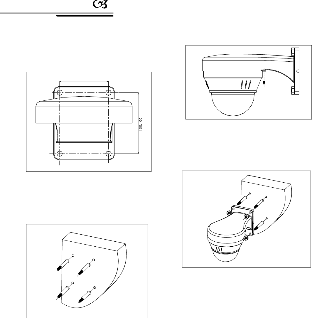
Picture2.2-2
Picture2.2-3
75.00
2Makethewallbracketasthemodelon
installationwall,anddrawthecentralposition
ofthedrillhole.(Aspicture2.2-2)
、
3PleasedrillfourinstallationholesforM8
metalexpandscrewwiththelashedelectricdrill
ontheinstallationsurface,andbesurewiththe
installationholeof75mmdepthapproximately
andM8expandmetalscrew.(Aspicture2.2-3)
、
4Getthewater-proofoutputcableofmini
domethroughthewallbracket,andmakethe
threescrewofcoverboardintheminidomeinto
theapertureonthebaseboard,thenturn15deg-
reesinclockwise,andbesurethatcentralposit-
ionofthetwoearholesofbaseboardandcover
boardarematched,andthenlockittightlyusing
theadditionalM3*5screw.
、
Installationinstruction
4
Picture2.2-5
6Connectthepowercable,videocableandRs485
control-cable.Asthepicturebelow.
、
5PlsmakethewallbracketaimsattheM8screw,
sothattheoutputcablewillbelockedintheholeof
motherboardbracket,andusetheM8screwtolock
thewallbrackettightly.Aspicture2.2-5.
、
Picture2.2-4
PDF created with pdfFactory Pro trial version www.pdffactory.com