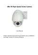
Mini IR High Speed Dome Camera User Manual Please read this manual thoroughly before use or installation and keep it handy for fureture reference
WARNINGS AND CAUTIONS WARNING TO REDUCE THE RISK OF FIRE OR ELECTRIC SHOCK, DO NOT EXPOSE THIS PRODUCT TO RAIN OR MOISTURE. DO NOT INSERT ANY METALLIC OBJECTS THROUGH VENTILATION GRILLS OR OPENINGS ON THE EQUIPMENT.
IMPORTANT SAFEGUARDS 1. Read these instructions before attempting installation or operation of dome device. 2. Keep these instructions for future reference. 3. Heed all warnings and adhere to electrical specifications. Follow all instructions. 4. Clean only with non abrasive dry cotton cloth, lint free and approved acrylic cleaners. 5. Should the lens of the camera become dirty, use special lens cleaning cloth and solution to properly clean it. 6. Do not block any ventilation openings.
INDEX 1 Product Introduction ...................................................................................................... 1 1.1 Package Contents ...................................................................................................... 1 1.2 Specification ............................................................................................................... 2 1.3 Performance Features ...............................................................................................
1. Basic Feature of RS-485bus ...................................................................................... 20 2. Mode of Connection and Terminal Resistance ........................................................... 20 Appendix Ⅳ Exception Handling ................................................................................... 21 Copyright Statement ........................................................................................................
1 Product Introduction 1.
1.
1.3 Performance Features PWM function. Intelligent IR illumination & power consumption is variable, dependant the zoom factor. 3D allocation. That screen coordinate location and zoom local are performed at the same time can be available. Privacy masking. 24 privacy masking areas can be random set (module support). Supported Protocols. Pelco-D/P; Others on special request. 4 path patterns. Each path can record 512 different instructions or 900s path operation. Manual control speed.
1.4 Function Description Alarm Linkage Intelligent dome camera supports 4 switch alarm inputs, 1 switch output and 1 digital output. When the dome camera has detected the alarm closed signal, it will run the preset action which can be one of the calling preset points or no action. Auto-adaptive to Protocol and Module The dome can auto-adaptive to the multi protocol and most of the module without changing the DIP switch.
(4) Targets are behind the glass covered with water droplets or dust; (5) Targets are moving quickly; (6) Monotonous large area targets, such as wall; (7) Targets are too dark or faint. BLC(Back Light Compensation) If the light of background is bright, the target in the picture may appear dark or as a shadow. BLC enhances exposure of the target in the center of the picture. The dome adjusts the iris according to the center of the pictures.
parameter, or check the related information through the OSD. Return to PTZ Function Return dome’s pan and tilt and camera zoom value to the control device. 2 Installation 2.1 Product Dimension 2.
2.3 Installation 2.4 Connection Connection of RS485 Before connecting, please turn off the power and read carefully the instructions of all connected devices. Please use the standard power we supply and don’t lengthen the power cable arbitrarily.
3. Instruction 3.1 Power On Action When initializing the system, the operation as left figure will run in 2 seconds. IR SPEED DOME PROTOCOL COMM DOME ID MODULE VERSION PAN TILT PELCO-D/P When restoring out-of-factory settings, please wait patiently. 2400.N.8.1 The operation as left figure will run in 1 minute. 001 This left figure means initializing the pan/tilt motor of speed dome camera. V1.2 INIT INIT POWER ON IR SPEED DOME PROTOCOL COMM DOME ID MODULE VERSION PAN TILT PELCO-D/P 2400.N.8.1 001 V1.
Press ZOOM- button to make the lens farther and minify the scene. Press ZOOM+ button to make the lens closer and magnify the scene. Focus After FOCUS- button is pressed, the object in vicinity will become clearer while the object far away will become ambiguous. After FOCUS+ button is pressed, the object far away will become clearer while the object in vicinity will be ambiguous. Iris Press IRIS- to gradually shrink the iris and decrease the image brightness.
3.4 Screen Character Operation Call preset 95 to enter the OSD, call preset 94 to exit the OSD. Up or Down: Move the option of the OSD, change the value on the OSD. Right: Enter the option, select the item or confirm. Left: Return to main menu or cancel. Zoom Display: x XXX, XXX is the present zoom of camera. Time Display: XXXX(year)-XX(month)-XX(day) Angle Display: XXX.XX(pan)/XXX.XX(tilt) IR Display: ☀means the IR display status is on.
4 OSD Menu 11
4.1 System
PRESET NO CALL PRESET PRESET 1: SAVE PRESET 2: BACK back. 001 Because some presets are used to realize special functions, they can not be set and called normally. 4.2.2 Scan SCAN SCAN SPEED SCAN SPEED: Scan speed includes setting the speed of limited points scan (A-B scan) and 5 360°scan. Its range is 1-9 grades. EXIT Note: The effective range of left and right boundary is 20-340°. 4.2.3 Guard Tour This dome camera can set 4 groups of guard tour.
4.2.4 Pattern PATTERN NO CALL PATTERN EXIT 1 Select the pattern needing to be edited. 1-4 pattern are effective. PATTERN NO CALL PATTERN 1 PATTERN NO: Factory default is 1. CALL PATTERN: Call the patterns having been edited. Left figure shows the status when entering to the pattern set. “XXX” means the quantity of operator’s running pattern, and 512 is the most amount of the instruction.
4.2.6 Other EXIT PARK MODE NONE PARK TIME 05 POWER ON ACT MEMORY RATIO SPEED ON AUTO FLIP ON PARK MODE: There are 13 actions of NONE, Pattern 1, Tour 1, 360 scan, AB scan, Preset 1-8 selectable. PARK TIME: The dome camera runs home position after a period of idle time which is home time and whose range is 1-60 mins.
4.3 Camera ZOOM LIMIT FOCUS MODE DIGITAL ZOOM ZOOM SPEED EXIT AUTO OFF HIGH ZOOM LIMIT: Display the maximum zoom position, which relates to that digital zoom is OFF or ON. FOCUS MODE: Auto and manual are selectable. DIGITAL selectable. ZOOM SPEED: Zoom speed has HIGH and LOW selectable. WB MODE: There are indoor, outdoor, auto, manual selectable. RED GAIN: It can only be adjusted under the condition that the WB mode is manual. And its range is 000-255.
4.4 IR IR MODE OUTPUT POWER TESTING TIME STANDBY POWER STANDBY TIME ILLUMINATION ON IR SWITCH ZOOM AMBIENT LIGHT EXIT AUTO 9 08S 8 20S 08L 05 IR MODE: It has auto, small light on, large light on, manual and off selectable. OUTPUT POWER: Its selectable range is 1-9 level. TESTING TIME: Its settable range is 2-15S. STANDBY POWER: IR power standby can be set to 1-9 level when the dome camera is in idle time, which can improve the life of IR lamps.
SCHEDULE: Action: There are preset 1-8, A-B scan, 360°scan, guard tour preset, pattern, no action selectable. Example of Schedule: START END ACT 00:00:00 00:00:00 NONE 00:00:00 00:00:00 NONE 00:00:00 00:00:00 NONE 00:00:00 00:00:00 NONE 00:00:00 00:00:00 NONE 00:00:00 00:00:00 NONE 00:00:00 00:00:00 NONE 00:00:00 00:00:00 NONE SAVE 1: 8 schedules can be set. First, select the schedule needing to be set and press the right key to enter the setting status.
Appendix Ⅰ Anti-lightning, Anti-surges This product is extremely air discharge and lightning protection with TVS tube technology, which can effectively prevent the transient lightning below voltage 6000V, surge and damages caused by other types of pulse signals.
● Please use a soft enough dry cloth or other alternatives to wipe internal and external surface. ● If dirt is serious, user can use a mild detergent. Any senior furniture cleaning products can be used to clean the under cover. Appendix Ⅲ Common Knowledge on RS-485 Bus 1.
Appendix Ⅳ Exception Handling Issue Possible Reason Solution After power is applied, Cable harness is improperly Verify that the orientation of the connected connector input there is no action Input power voltage is too low Verify the voltage of the input power (self-test) and no video image. Power supply does not work Change a new power supply Self-test is normal, but Wrong communication dome cannot be settings controlled.
Copyright Statement This copyright merely belongs to the manufacturer. Without permission, please don’t plagiarize or copy the contents of this book in any form or by any means. The company follows the policy of continuous development. Therefore, the company reserves the right to modify or improve the products described in this manual without notice. The content of manual is offered according to the "current state".