
Use and Care Manual

6
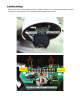
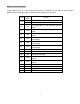
4. Camera ID Setting
This speed dome camera requires setting of the ID before use. The ID set by an 8-segment ID setup
switch (SW2) on the main PCB. The binary system ID setup range is : 00000000-1111111. Digital “1”
equals switch ON, and digital “0” equals OFF, for example:
The positions from 1 to 8 of SW2 are used for camera ID setting.
Switch SW2
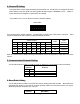
This ID setup switch shows 10010011,corresponding to ID201 when using Pelco D protocol. Each
camera ID setting and OSD number (if used) are entered as below:
Switch Position
OSD
CAM
Selection
1 2 3 4 5 6 7 8
OFF OFF OFF OFF OFF OFF
OFF OFF
000 CAM-000
ON OFF OFF OFF OFF OFF
OFF OFF
001 CAM-001
OFF ON OFF OFF OFF OFF OFF OFF 002 CAM-002
ON ON ON ON ON ON ON ON 255 CAM-255
Other ID numbers can be setup according to the Address Code Correspondence Table at the end of the
manual.
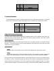
5. Communication Protocol Setting
The #3 & #4 positions of SW1 on PCB are used for setting the communication protocol as below:
Switch
Position
Protocol
3
4
OFF
OFF
State Standard
OFF
ON
PELCO-D
ON
OFF
PELCO-P
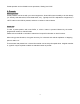
6. Baud Ratio Setting
The #5 & #6 positions of SW1 on the PCB are used for setting baud ratio as below. Baud ratio is the
speed that the modem in your DVR or controller operates. Match the PTZ’s baud rate to your device.
9600 bps (baud per second) is very common.
Switch
Position
Baud Ratio
ON
1
2
3
4
5
6
7
8