Model SLC-177 Weatherproof Pan/Tilt 22X Optical Zoom Speed Dome Owner’s Manual 15540 Herriman Blvd. Noblesville, IN 46060 - Customer Support 1-800-774-0284 www.security-labs.
TABLE OF CONTENTS Important Safety Measures 2 1) Dome Wiring 3 2) Installation 4 3) Switch Settings 5 4) Camera ID Settings 6 5) Communication Protocol Setting 6 6) Baud Rate Setting 6 7) Camera Selection 7 8) Basic Function & Operation 8 9) Presets 9 10) Tour Groups 10 11) Horizontal Scanning 11 12) Pan/Tilt/Zoom Lens Matching 12 13) Auto Flip 12 14) Screen Characters 12 15) Display Zoom 12 16) Camera Specifications 13 17) SW2 Camera Address Code Switch Settings 14 18) O
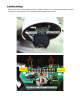
1. Wiring CAUTION Please confirm the supply voltage meets requirements of the dome camera’s power supply. the Wiring for Dome System 100 feet of CAT5E twisted pair cable, and a 12VDC power supply is included with your dome camera. Additional CAT5E cable can be purchased from a variety of stores or distributors and easily spliced to your cable. Up to 1,000 feet of cable can be successfully used on an installation. More distance can be achieved with the use of an amplifier.
2. Installation Requirements 1) To ensure proper operation make sure the 12 VDC power supply packed with your dome camera is securely connected to an indoor 120 VAC outlet near the location of the dome. Power Supply is not made for outdoor use. The use of a UL Approved extension cord is acceptable. Please consult your local electrical codes for specific information. 2) Secure the included wall or ceiling (pendant) bracket to hold a minimum of five times the total weight of your dome assembly.
3. Switch Settings Please confirm the communications protocol (i.e Pelco-D, Pelco-P, etc.), baud ratio & camera ID match your DVR or control system.
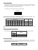
4. Camera ID Setting This speed dome camera requires setting of the ID before use. The ID set by an 8-segment ID setup switch (SW2) on the main PCB. The binary system ID setup range is : 00000000-1111111. Digital “1” equals switch ON, and digital “0” equals OFF, for example: The positions from 1 to 8 of SW2 are used for camera ID setting. Switch SW2 ON 1 2 3 4 5 6 7 8 This ID setup switch shows 10010011,corresponding to ID201 when using Pelco D protocol.
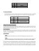
5 OFF OFF ON ON 6 OFF ON OFF ON 1200 bps 2400 bps 4800 bps 9600 bps 7. Camera Selection The #7 & #8 positions of SW1 on PCB are used for the zoom module camera selection. The protocol used for the included zoom module is equivalent to the LG standard and is preset at our factory. #7 Position OFF OFF ON ON #8 Position OFF ON OFF ON Camera Zoom Module SONY Zoom Module CNB Zoom Module HITACHI Zoom Module LG Zoom Module 8.
Preset operation can be divided into two processes, "Setting" and "Call". 9. Presets Entering Presets Preset positions can be set with your control equipment. Some DVRs have the ability to do this directly (i.e. Security Labs 260 series, Piczel 5090 series, etc.).
Specific Preset Commands Preset numbers from 31 to 58 are defined as specific commands and not used as single presets. Please refer to the following table for details of these presets and commands.
. Tour Groups Tour group scanning combines auto scanning between a series of presets with a certain sequence and a certain speed, and stay a certain time at each preset. The scanning speed and the stay time at each preset can be set according to the user's actual requirements. The presets arranged by a certain sequence combine to make a tour group. A total of eight tour groups can be set, named from preset numbers #31 to #38. Each group may include multiple presets from 2 entries to 64 entries.
Stay time for each preset of the tour group can be setup as 3 seconds, 5 seconds or 7 seconds. [43]+[Call]--------- setting stay time for preset of the group is 3 seconds [44]+[Call]--------- setting stay time for preset of the group is 5 seconds [45]+[Call]--------- setting stay time for preset of the group is 7 seconds If you wish to setup the stay time for preset as 7 seconds, input "45" on the control keyboard, and then press the key [call]. 11.
[41]+[Call]--------- setting scanning with middle speed [42]+[Call]--------- setting scanning with high speed If you wish to setup the horizontal scanning with middle speed, input “41” on the control keyboard, then press the key [call]. 12. Pan/Tilt Speed and Zoom Lens Automatic Matching This speed dome has the function of pan/tilt speed and zoom lens automatic matching. When the function is ON, the pan/tilt speed will auto decrease when the zoom lens is increased helping you track objects far away.
16. Camera Specifications Image Device: 1/4" Color Sony ExView II™ Picture Elements: NTSC:1020x508, PAL:1020x596 Resolution: 600 TVL Min. Illumination: 0.05 Lux / F1.6 S/N Ratio: More than 48dB Electronic Shutter: NTSC:1/60~1/100,000 Lens Furnished: 22x Auto Focus Zoom (3.9~85.8mm / F1.6~3.7) Digital Zoom Ratio: Basic 16x (Total Zoom Ratio 352x), 2x~16x variable Min. Shooting Distance: 0.01m (Wide), 1.
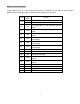
ID Switch (SW2) settings used with *PELCO D protocol *See Note 14
*Note: The above reference table is for ID switch settings when using Pelco D protocol. Pelco P considers binary 0 to equal decimal 1, so each consecutive number should shift one address to the left when using Pelco P. Example: 1=00000000, 2=10000000, 3=01000000, 4=11000000, etc. 19. Optional Accessories 1) Pendant Mount (Ceiling) Bracket 2) Wall Mount Bracket 3) Pole Mount Bracket 4) Corner Mount Bracket Wall Mount Ceiling Mount Corner Mount Pole Mount Check www.security-labs.