24 HR REAL TIME / 960 HR TIME LAPSE RECORDER User’s Guide SL820 15540 Herriman Blvd. - Noblesville, IN 46060 1-800-774-0284 - www.security-labs.com Be sure to read carefully and follow all the SAFETY INFORMATION on pages i, ii, iii. Keep the manual in a safe place for future reference.
Safety information CAUTION RISK OF ELECTRIC SHOCK DO NOT OPEN CAUTION: TO REDUCE THE RISK OF ELECTRIC SHOCK, DO NOT REMOVE COVER (OR BACK). NO USER-SERVICEABLE PARTS INSIDE. REFER SERVICING TO QUALIFIED SERVICE PERSONNEL. The lightning flash with arrowhead symbol, within an equilateral triangle, is intended to alert the user to the presence of uninsulated “dangerous voltage” within the product’s enclosure that may be of sufficient magnitude to constitute a risk of electric shock.
home, consult your video dealer or local power company. For video products intended to operate from battery power, or other sources, refer to the operating instructions. 6 Overloading- Do not overload wall outlets of extension cords as this can result in a risk of fire or electric shock. Overloaded AC outlets, extension cords, frayed power cords, damaged or cracked wire insulation, and broken plugs are dangerous. They may result in a shock or fire hazard.
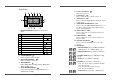
Contents Locations of controls and indicators .............................................................................................. 1 Front Panel .............................................................................................................. 1 Digital Display ......................................................................................................... 2 Back Panel .............................................................................................................
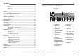
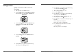
Digital Display 6 7 8 9 1 1 2 3 4 5 6 7 8 9 2 3 4 5 2 Operation Indicators display the actual operation mode. Operation Mode Record (REC) Record pause (REC PAUSE) Playback (PLAY) Still image (STILL) Fast forward (FF) Rewind (REW) CUE (CUE)+ Review (REVIEW)+ Slow (Pause Still + FF, Pause Still + REW) Indicator REC REC + 10 11 12 + 13 + + + Cassette indicator : Comes on when a cassette is loaded. Record check indicator : REC Flashes on during record check.
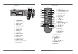
Back Panel 1 2 3 4 5 6 7 8 9 10 11 12 13 14 15 16 4 Remote Control AC POWER CORD WARNING OUT terminal SERIES IN terminal COM terminal SERIES OUT terminal SW OUT terminal VIDEO OUT jack VIDEO IN jack AUDIO IN jack TAPE END terminal PANIC IN terminal COM terminal ALARM OUT terminal ALARM IN terminal MIC(microphone input) jack AUDIO OUT jack Time Lapse Video Cassette Recorder 18 19 20 21 22 23 24 Time Lapse Video Cassette Recorder 1 POWER button 2 PLAY/STILL TRACKING + button 3 PLAY/STILL TRACKING - bu
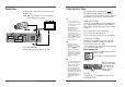
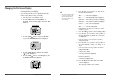
Connections Video Cassettes Tapes Connect the video camera and monitor TV as shown in the figure below. NOTE : Make sure to turn the power off on all devices before making the connections. Use only video cassette tapes bearing the logo. This VCR was primarily designed for use with T-120 cassette tapes. It is recommended to use T-120 VHS or T160 VHS video cassette tapes for optimal performance. ✔ • If you try to record on a cassette without the erasureprevention tab, the VCR will eject the cassette.
Types of On-screen displays and Display Sequence • If the VCR is in timer recording stand-by mode (the “ ” indicator is displayed on the display panel), the on-screen displays will not be available. First press the STANDBY/ON(POWER) button, to cancel the recording stand-by mode, then proceed with the VCR programming. When finished, press the STANDBY/ON(POWER) button again to return the VCR to timer recording stand-by mode. • When a menu is displayed, recording will not be possible.
Setting the Clock Example: To set the clock to April 12, 2002 at 9:30 Clock Setting 1 2 3 10 Turn the power on to all devices used. Press the MENU button, the initial MENU is displayed. The arrow mark ( ) is located in “VCR Mode Set”. Initial MENU Press the SHIFT button, the VCR MODE SET menu is displayed. The arrow mark ( ) is located in “Clock Set”. 4 Press the SHIFT displayed. 5 Press the SET - (or +) button to set the hours (eg : 09), then press the SHIFT button.
Changing the On-Screen Display Selecting the On-screen Display You can select whether or not to display the time, date, frame counter, alarm counter, counter title. 1 Turn the power on to all devices used. 2 Press the MENU button. The initial MENU is displayed. The arrow mark ( ) is located in “VCR Mode Set”. Initial MENU ✔ 6 • The items for which “YES” is set are recorded. The items for which “NO” is set at step 6 above are not recorded.
Normal Recording ✔ • If the Repeat Rec Set is set to “NO” in the REC MODE SET menu , recording will continue to the end of the tape, then stop and the tape will be ejected. Normal Recording ✔ Record Pause 1 2 • During pause, the image appears on screen but it is not recorded. Recording can be interrupted temporarily. 1 Press the PAUSE/STILL button during recording. 3 ✔ • The recording speed is displayed on-screen and on the display panel.
Program Timer Recording There are two program timer recording methods, daily recording or recording on certain days of multiple weeks (weekly recording). Example 1 : To record on every Thursday from 10 : 00 to 18 : 00 , in 18-hour mode (recording speed) 1 2 3 Make sure that the set date and time are correct. Load a cassette tape with erasure prevention tab in place. Press the MENU, SHIFT , SHIFT , SHIFT buttons in sequence to display the TIMER PROGRAM SET(1) menu.
Example 2 : To record everyday from 10 : 00 to 18 : 00, in 18-hour mode (recording speed) 1 2 Repeat steps 1 to 3. Press the SHIFT button, until the cursor is on “DLY”. The MENU below is displayed. To Cancel a Program Timer Recording 1 2 3 4 5 3 Repeat step 1 above. Press the SHIFT (or ) button until the cursor is located in the “Y” corresponding to the timer recording to cancel. Press the SET - (or +) button, to select “N”. Press the MENU button three times until the normal screen is displayed.
Alarm Recording • Auto / 20sec / 30sec / 40sec / 01min / 02min / 3min / 5min / 10min / 15min / 20min / 25min / 30min : Recording for the set duration. (min : minute) • T.END : Records until the tape end is reached when there is alarm trigger input. Alarm Recording Setting Alarm recording is performed when there is an input (trigger) at the ALARM IN terminal, “ ” is displayed on the display panel. 1 Make all necessary connections.
Panic Recording This feature is similar to an alarm recording, but the recording time is not pre-selected. When there is a panic input at the PANIC IN Terminal, recording will start and continue for up to 2 hours. Connecting to a Monitor for Alarm Recording Series Recording Using 2 VCRs or more, the series recording function lets you switch recording from one unit to the next (only with VCRs of the same model as this one).
Autorepeat Recording 4 Set the security lock on VCR No.1. Autorepeat Recording • When the end of the tape on VCR No.1 is reached, the output at the SERIES OUT terminal will switch signal. This will start recording on VCR No.2, the tape will stop and be ejected on VCR No.1. The same tape can be recorded over many times. Please note that if you activate this feature you will lose the entire previous recording. 1 Press the MENU, SHIFT , SHIFT button in sequence to display the REC MODE SET menu.
Normal Playback ✔ • A slow motion effect or accelerated playback effect can be achieved by using a slower or faster playback speed than the speed used for recording. Normal Playback ✔ Audio Playback 1 2 3 • Noise will appear in the image when audio playback is used in 18hour or 24-hour mode. Audio playback is only possible in 2-hour, 6-hour, 18hour and 24-hour modes. The playback speed has to be the same as the recording speed, for normal playback of the audio.
Special Playback ✔ Picture Search ✔ Recording Check 1 • During recording check operations, recording is suspended momentarily. During recording, press the REC CHECK button. • During picture search, noise (horizontal bars) will appear in the picture. • The image can be seen while the tape is advanced (or rewound) at high speed. • The sound is muted. 2 ✔ • If still mode continues for 5 minutes or more, the VCR will go into stop mode to avoid damaging the tape.
Other Functions ✔ Alarm Scan 1 2 Repeat steps 1 to 3. Press the SHIFT button to search forward or in reverse without entering a specific alarm number. • The display returns to the normal screen. • The VCR will advance (or rewind) the tape at high speed, and playback the first 5 seconds of every alarm recording. • To cancel the alarm scan mode, press the STOP button. 3 While the desired recording is being played back, press the PLAY button. • Playback will start, and alarm scan is cancelled.
Setting the Security Lock (Set Lock) Setting the SW Out Terminal Output • While the security lock is engaged, all commands are disabled. The security lock function is designed to prevent accidental stopping of recording if the STOP button is pressed inadvertently. 1 Set the SET LOCK switch to “ON” position. • The security lock should not be engaged while a menu is displayed. 2 Synchronization pulses for a multiplexer can be obtained from the SW OUT terminal.
✔ Setting the Buzzer Checking the Alarm Recording Times In the following cases, the buzzer will be heard approximately 5 times. 1 2 1 2 - If the REC button is pressed while a cassette without erasure-prevention tab is loaded. Press the MENU button to display the initial MENU. Press the SHIFT button to select VCR Mode Set. The VCR MODE SET menu is displayed. ✔ • The data for the previous alarm recordings, past 35, is erased.
Setting In/Out terminals 1 2 3 4 5 6 7 36 Press the MENU button to display the initial MENU. Press the SHIFT button to display the VCR MODE SET menu. Press the SHIFT button to move the arrow mark ( ) to In/Output Set. Press the SHIFT button to display the IN/OUTPUT SET menu. Press the SHIFT button to move the arrow mark ( ) for the desired item. Press the SHIFT button to set “N/C” or “N/O”, “High” or “Low”. Press the MENU button three times, the normal screen is displayed.
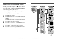
• SW OUTPUT Terminal While recording, a pulse signal(DC 5V) is output at the SW OUT terminal after each recording period. This terminal is usually connected to the sync input or sync trigger on a multiplexer (see Page 33). 1) Low If you are also using a Multiplexer, use the following diagrams as a guide to connecting the VCR for normal or alarm recording.
Daily Inspection The following daily inspections are recommended in order to assure long-term and trouble-free operation of the unit. The daily inspections are particularly important if using autorepeat recording. Connecting to a Multiplexer for Alarm Recording ✔ • If the security lock is engaged, it has to be released before proceeding with the inspection. MULTIPLEXER • If any problem is discovered during the inspection,unplug the power cord and consult your dealer.
Troubleshooting Guide SYMPTOM If the unit does not operate normally when you follow the instructions indicated in the manual, please refer to the table below. SYMPTOM No power. POSSIBLE CAUSE - Connect the power cord firmly into the wall outlet. - This is normal, not a malfunction. No image displayed on the monitor TV. The connections are not correct. The power to the camera and/or monitor TV is not turned on. - Check that all connections are correct. - Turn all connected devices power on.
Specifications General Specifications Recording method Audio recording Tape speed Specified video cassette tape Recording/playback time Fast forward/rewind time Television system Video Recording method Video input Video output Horizontal resolution MAINTENANCE LOG Dual-azimuth 4-head rotating helical scanning system In 2, 6, 18 and 24 hour modes 33.
Warranty Security Labs Incorporated warrants each new electronic product manufactured by it to be free from defective material and workmanship and agrees to remedy any such defect or to furnish a new part (at the Company’s option) in exchange for any part of any unit of its manufacture which under normal installation, use and service disclosed such defect, provided the unit is delivered by the owner to us or to our authorized distributor from whom purchased or authorized service station intact, for our exam