Programming Guide XT SERIES™ Panels
MODEL XT30/XT50 Programming GUIDE When using the XT30/XT50 Series control for any listing organization’s approved methods, refer to this manual and the XT30/XT50 Installation Guide. These documents outline the installation and programming requirements of all applications for which the XT30/XT50 is approved.
Table Of Contents Introduction...............................................................1 1.1 1.2 1.3 1.4 1.5 1.6 1.7 1.8 1.9 1.10 Before You Begin.........................................................1 Programming Information Sheet...................................1 Getting Started............................................................1 Initializing the Panel.....................................................1 Program from any Keypad Address...............................
Table of Contents Messaging Setup......................................................11 5.1 5.2 5.3 5.4 5.5 5.6 5.7 5.8 5.9 5.10 5.11 5.12 5.13 5.14 Messaging Setup.......................................................11 Enable Messaging......................................................11 System Name............................................................11 Destination 1.............................................................11 Destination 2..................................................
Table Of Contents 9.4 9.5 9.5.1 9.5.2 9.5.3 9.5.4 9.5.5 9.5.6 9.5.7 Bell Output................................................................20 Bell Action.................................................................20 Fire...........................................................................20 Burglary....................................................................20 Supervisory...............................................................20 Panic...........................................
Table of Contents 13.10.3 13.10.4 13.10.5 13.10.6 13.10.7 13.10.8 13.10.9 13.10.10 13.10.11 13.11 13.12 13.12.1 13.12.2 13.12.3 13.13 13.14 13.15 13.16 13.17 13.18 Key Fob Supervision Time..........................................29 Number of Key Fob Buttons ............................... 29 Key Fob Button Selection (Four Buttons).....................29 Key Fob Button Selection (Two Buttons) ................. 29 Button Action............................................................30 Button Press Time.
Table Of Contents This page intentionally left blank.
Introduction Introduction 1.1 Before You Begin Before starting to program, we recommend you read through the contents of this manual. The information in this document allows you to quickly learn the programming options and operational capabilities of the XT30/XT50 panel. After this Introduction, the remaining sections describe the functions of each programming menu items along with their available options.
Introduction 1.3 Programming Menu You are now ready to start programming the XT30/XT50 panel. Pressing the COMMAND key scrolls you through the programming menu items listed below.
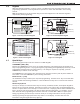
Introduction 1.6 Keypads DMP offers multiple keypads in a variety of styles. All DMP 32-character keypads provide the same programming capabilities. Each keypad and its operation are shown and described in the following sections. Note: Programming can not be accessed using an Icon Series keypad. Use a 32-character keypad to complete the panel programming.
Introduction When there are more than four response options available, press the COMMAND key to display the next one to four options. Pressing the Back Arrow key allows you to review the previous four choices. The Select keys/areas are also used for choosing a section from the programming menu. Press any Select key or touch the Select Area when the programming section name you want displays.
Introduction 1.10 Keypad Displays Current Programming Each programming prompt displayed at the keypad shows the currently selected option in the panel memory. These options are either shown as a number, a blank, or a NO or YES. To change a number or blank to a new number, press any top row Select key or touch any Select Area. The current option is replaced with a dash. Press the number(s) on the keypad you want to enter as the new number for that prompt.
Initialization Initialization 2.1 Initialization Initialization This function allows you to set the panel’s programmed memory back to the factory defaults in preparation for system programming. After you select YES to clear a section of memory, the panel asks if you are sure you want to clear the memory. This is a safeguard against accidently erasing part of your programming. No memory is cleared from the programming until you answer YES to the SURE? YES NO prompt.
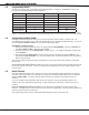
Communication Communication 3.1 3.2 COMMUNICATION Communication The Communication section allows you to configure the communication settings for the XT30/XT50 panel. After choosing the Communication Type, continue through the list of options. Account Number Account NO: Enter the account number sent to the receiver. DD, NET, CELL - The range of account numbers for Digital Dialer, Network, and Cell is 1 to 65535. For account numbers of four digits or less, you do not have to enter leading zeros.
Communication 3.7 Test Time 00:00 AM 3.8 NET TEST DAYS: 1 DIAL TST DAYS: CELL TEST DAYS: 1 Enter how often the panel test report is sent to the receiver for each communication 1 type programmed. Enter from 1 to 60 days. Enter zero to disable the test report. Default is 1 (one) day. These options only display if a test time is entered and that particular communication method is being used. 3.9 Test Time PM Press COMMAND to enter the Test Time.
Communication 3.16 O/C User NO Yes 3.17 First Phone NO. - Opening/Closing and User Reports YES enables Opening/Closing, Door Access, Schedule and Code Changes, Bypass, and Sensor Reset reports by user to be sent to the receiver. Default is YES. First Telephone Number Enter the first number the panel dials to send reports to a receiver. A phone number may contain two lines of 16 characters to equal 32 characters. You can program a three-second pause in the dialing sequence by entering P.
NETWORK Options Network Options Network Options are provided to define the network configuration for the panel. This information will be used during communication of messages via network or email. Note: IP addresses and port numbers may need to be assigned by the network administrator. When entering an IP, Gateway, or Subnet Mask address be sure to enter all 12 digits and leave out the periods. For example, IP address 192.168.000.250 is entered as 192168000250. 4.1 DHCP 4.
messaging setup Messaging Setup 5.1 MESSAGING sETUP Messaging Setup This section allows you to enter the information needed to receive messages directly from the panel via email and cellular communication. All of the name and address options below allow up to 32 lowercase characters to be entered. System Name will display with initial caps.
messaging setup 5.8 EMAIL O/C NO Yes Email O/C Select YES to allow the panel to send Opening and Closing reports via email. Default is NO. This prompt appears only if any destination above is an email address. 5.9 SMS O/C NO Yes SMS O/C Select YES to allow the panel to send Opening and Closing messages to a cell phone via SMS protocol. Default is NO. This prompt appears only if any destination above is a cell phone number.
Remote Options Remote Options 6.1 Remote Options Remote Options This section allows you to enter the information needed for Remote Command/ Remote Programming operation via a dial up or network link. A description of the Remote Options follows: 6.2 Remote Key RMT Key: This option allows you to enter a code of up to eight digits for use in verifying the authority of an alarm or service receiver to perform a remote command/ programming session.
Remote Options 6.7 SVC RcVR NO Yes Service Receiver Authorization YES enables remote commands and programming to be accepted from a secondary service receiver other than the alarm SCS-1R Receiver. The Remote Key option can also be required. With YES selected, the panel requests the service receiver key the first time it is contacted by the service receiver. The panel retains this service receiver key in memory and accepts remote commands from the service receiver.
System Reports System Reports 7.1 System Reports System Reports This function allows you to select the reports the XT30/XT50 will send to the receiver. 7.2 OpEn/ClosE No YES 7.3 Abort NO Opening/Closing Reports NO - Will not send Opening/Closing Reports. YES - Will cause the panel to send Opening/Closing Reports for each programmed area.
System Options System Options 8.1 System Options System Options This section allows you to select system wide parameters used in the operation of the XT30/XT50 system. A description of each System Option follows: 8.2 SYSTEM: ALL/PERIM System This configures the panel as either a four Area system, an All/Perimeter system AREA A/P H/A (Perimeter/Interior), or a Home/Away system (Perimeter, Interior, and Bedrooms). Zones must be assigned to Bedrooms for the area to be active.
System Options 8.6 Exit Delay: 60 Exit Delay Enter the Exit Delay time for all Exit type zones. When the exit delay time starts, all activity on exit and burglary zones is ignored until the exit delay expires. The keypad displays the Exit Delay time countdown and annunciates the Exit Delay tone at 8 second intervals until the last 10 seconds when annunciation is at 3 second intervals. The exit delay can be from 45 to 250 seconds. Default is 60 seconds.
System Options 8.11 Zn Acty Hrs: 0 Zone Activity Hours This option provides supervision of a person living alone for non-activity. Enter the number of hours, 0 to 9, allowed to elapse without a disarmed zone being tripped before a message is sent to the receiver. Default is 0 (zero). When the system is disarmed, the timer begins to countdown the number of hours programmed. Each time activity occurs, the timer restarts the countdown.
System Options 8.14 8.15 8.15.1 Time Dsp NO Yes Time Display HOUSE CODE: House Code 0 DET JAMNG no yes 8.15.2 8.17 When using a DMP wireless system, enter a house code between 1 and 50 for the wireless system to use. The DMP wireless receiver automatically programs the house code into the wireless transmitters when the unique transmitter serial number is programmed into the panel. See Wireless programming in Zone Information.
Bell Options Bell Options 9.1 Bell Options BELL Options This section allows you to program the panel bell output functions. 9.2 Bell Cutoff: 5 Bell Cutoff Time Enter the maximum time from 1 to 15 minutes the Bell Output remains on. If the Bell Output is manually silenced or the system is disarmed, the cutoff time is reset. Enter zero to provide continuous bell output. Default is 5.
Output Options Output Options 10.1 Output Options OUTPUT Options This section allows you to program panel output options. Switched Ground (open collector) outputs are available using the 4-wire output harness on the XT30/XT50 board. Wireless outputs are available when using the built-in 1100 Series Receiver of the XT50 or an 1100D Wireless Receiver with the XT30. Refer to the XT30/XT50 Installation Guide (LT-0624) for complete information.
Output Options 10.6 Entry Out: 0 Entry Output This output turns on at the start of the entry delay time. The output turns off when the area disarms or the entry delay time expires. Enter 0 (zero) to disable. 10.7 Exit Out: 0 Exit Output This output turns on any time an exit delay time starts. The output turns off when the system arms or when the arming has been stopped. Enter 0 (zero) to disable. 10.
Output Information Output Information 11.1 Output Information OUTPUT info This section allows you to program and name wireless outputs into the panel when using an 1100D/1100DH/1100DI Wireless Receiver with an XT30 panel or the built-in receiver of the XT50. Wireless outputs are also available on the XT50 when using an onboard receiver. Output Information only displays when a House Code (1-50) is entered in System Options programming. 11.2 Output Number Output No: - Enter an output number.
Area Information Area Information 12.1 Area Information Area Information This section allows you to assign functions to individual areas for XT30 and XT50 panels. All non-24-hour zones must be assigned to an active area. See the section on Zone Information. Activate an area by assigning it a name. A name is given to each active area in place of a number to assist the user during arming and disarming. 12.2 Area No: - Area Number INT PERIM Enter the number of the area to program.
Zone Information Zone Information 13.1 Zone Information Zone Information This allows you to define the operation of each protection zone used in the system. 13.2 Zone Number Zone No: - Enter the number of the zone you intend to program. Press COMMAND to enter a zone name. Refer to the Enter Alpha Characters section. Keypad Address Zone Numbers 1 11-14 2 21-24 3 31-34 4 41-44 5 51-54 Note: Use zone numbers 31 to 34 or 41 to 44 with 1100 Series Key Fobs or DMP wireless output modules.
Zone Information If you select Blank, Night, Day, Exit, Auxiliary 1, or Auxiliary 2 as the Zone Type, the zone must be assigned to an area. If you select Fire, Panic, Emergency, or Supervisory as the Zone Type, these are 24-hour zones that are always armed and no area assignment is needed. Press COMMAND to continue.
Zone Information areas toggle between the armed or disarmed condition. When restored to normal, no action occurs. When the zone is opened from a normal (disarmed) state, a trouble is reported. When opened from a shorted (armed) state, an alarm is reported and the zone is disabled until you disarm the area(s) from either a keypad or Remote Link™ computer. ARM - When the zone is shorted, the programmed areas are armed. When restored to normal, no action occurs.
Zone Information 13.9.2 CONTACT: INTERNAL Contact This option displays if the serial number entered is for an 1101 or 1103 Universal Transmitter or 1114 Wireless Four-Zone Expander. Press any top row key to select the contact. INT EXT This option displays when programming an 1101 or 1103 Transmitter. Select INT to use the internal reed switch contacts. Select EXT to connect an external device to the 1101 or 1103 terminal block. Default is INTERNAL.
Zone Information 13.10 Series Key Fobs For an 1100 Series Key Fob set the House Code from 1 to 50. See House Code programming in System Options. Only zones 31‑34 or 41-44 can be programmed as 1100 Series Key Fob zones. Refer to the 1100 Series Key Fob Programming Sheet (LT-0706) supplied with the 1100D Wireless Receiver and the 1100 Series Key Fob Install Guide (LT-0703) as needed.
Zone Information 13.10.7 Action: xxxxxxx Button Action This option specifies the Button Action for an individual key fob button. The default action for the button selected is displayed. Press any Select key to display the Button Action options. To view more options press the COMMAND key. arm dis tgl sta ARM (Arm) - Arms selected areas and force arms bad zones. DIS (Disarm) - Disarms selected areas. TGL (Toggle Arm) - Toggles arm/disarm for selected areas and force arms bad zones when arming.
Zone Information 13.10.11 Action: Output Action This option allows you to define the output action (STD, PLS, MOM, TGL, OFF) for the selected output number. The default is Steady. STD Pls Mom Tgl STD (Steady) - The output is turned on and remains on. PLS (Pulse) - The output alternates one second on and one second off. MOM (Momentary) - The output is turned on only once for one second. TGL (Toggle) - The output alternates between the on state and off state. Each button press toggles the output state.
Zone Information 13.12.1 MSG: Trouble Message To Transmit You can send two report types to the receiver: Alarm and Trouble. These are represented by the characters A and T. Press any Select key to display the zone report options. A T l - ALARM - Selecting A allows an alarm report to be sent to the receiver and the bell output to activate according to zone type. See the Bell Action section. The zone name appears in the panel’s alarmed zones status lists.
Zone Information A report of a swinger bypass is sent to the receiver if Bypass Reports has been enabled. See the Bypass Reports section. Bypassed zones are automatically reset when the area they are assigned to is disarmed. All bypassed 24-hour zones are reset when the system is disarmed. 13.14 Prewarn Address Prewarn: 12345 Option is only shown for an Exit zone. At the start of the entry delay, all keypad addresses display ENTER CODE:-.
Zone Information Stop 14.1 Stop Stop At the STOP prompt, pressing any Select key allows you to exit the programmer function of the XT30/XT50 panel. When selected, the panel performs an internal reset and exits the programmer. The Stop function causes the following conditions to occur: • • • The system is DISARMED All 1100 Series DMP Wireless transmitters are reset to NORMAL The panel’s Status List is CLEARED During the Stop function, all keypad displays are momentarily disabled for two seconds.
Zone Information Appendix This section of the XT30/XT50 Programming Guide provides additional zone and system information. 16.1 Status List The Status List is the current status of the system or records of recent system events that display on alphanumeric keypads. For example, in Home/Away systems you may see the display SYSTEM READY. If an event were to occur on the system, such as an AC failure, the keypad would also display the AC POWER -TRBL message.
Appendix Panel Settings Hitting a top row key will allow access to the MAC Address, Serial Number, Panel Model, and Firmware Version. MAC Address Short for Media Access Control address. This hardware address uniquely identifies each network node. Not to be confused with an IP address, which is assignable. The MAC address is the panel on-board network hardware address. Press any top row Select key to display the panel MAC address. Press the COMMAND key to view the next prompt.
Appendix 16.5 Using the Walk Test The XT30/XT50 panel provides a walk test feature that allows a single technician to test all the protection devices connected to zones on the system. Conduct the Walk Test within 30 minutes of resetting the panel. The Walk Test automatically ends if no zones are tripped for 20 minutes. TEST IN PROGRESS displays at all keypads. When five minutes remain, TEST END WARNING displays. If any areas are armed the Walk Test does not start and SYSTEM ARMED displays.
Appendix 16.6 Keypad Speaker Operation When using LCD Keypads, the panel provides distinct speaker tones from the keypad for Fire, Burglary, Zone Monitor, and Prewarn events. The list below details the conditions under which the speaker is turned on and off for each event. Fire On - Fire zone alarm and Bell Output are ON. Off - Alarm Silence or briefly when a key is pressed. Burglary On - Burglary zone alarm and Bell Output and is ON. Off - Alarm Silence or briefly when a key is pressed.
Action = This function not available for this zone type. S S 0 0 0 0 A A A A 0 0 T T S S S 0 0 0 – T – Y Y Y Y Y Y Y Y Y Y Y 240 240 240 240 240 240 240 240 240 240 240 N N N N N N N N N N N Outputs = 1 to 4, 31 to 34, or 41 to 44.
Appendix 16.10 Common Keypad Messages Message Meaning Possible Solutions The user code you have entered is not recognized by the system. Check the user code and try again. CLOSING TIME The schedule has expired but the system has not been armed. Users still on the premise should arm the system or extend the schedule to a later time. AC TROUBLE The system is not getting proper power. Check that the AC connections are good. BATTERY TROUBLE The battery is either low or missing.
California State Fire Marshal (CSFM) ETL: ANSI/SIA CP-01 False Alarm Reduction ANSI/UL 1023 Household Burglar ANSI/UL 985 Household Fire Warning ANSI/UL 1635 Digital Burglar FCC Part 15 ID: CCKPC0096 FCC Part 68 Registration ID CCKAL00BXT50 Industry Canada ID: 5251A-PC0096 800-641-4282 INTRUSION • FIRE • ACCESS • NETWORKS www.dmp.com 2500 North Partnership Boulevard Made in the USA Springfield, Missouri 65803-8877 LT-0981 1.01 © 2008 Digital Monitoring Products, Inc.